Posted on

Hyundai Owner Manual vs Service Manual: What Most Drivers Get Dangerously Wrong

digital Hyundai owner manual and service manual comparison displayed on laptop screens

Most Hyundai drivers never realize they are using the wrong manual until something breaks. Grabbing an owner manual when you actually need a service manual can lead to missed torque specs, wrong fluid grades, and botched repairs that cost far more to fix later.

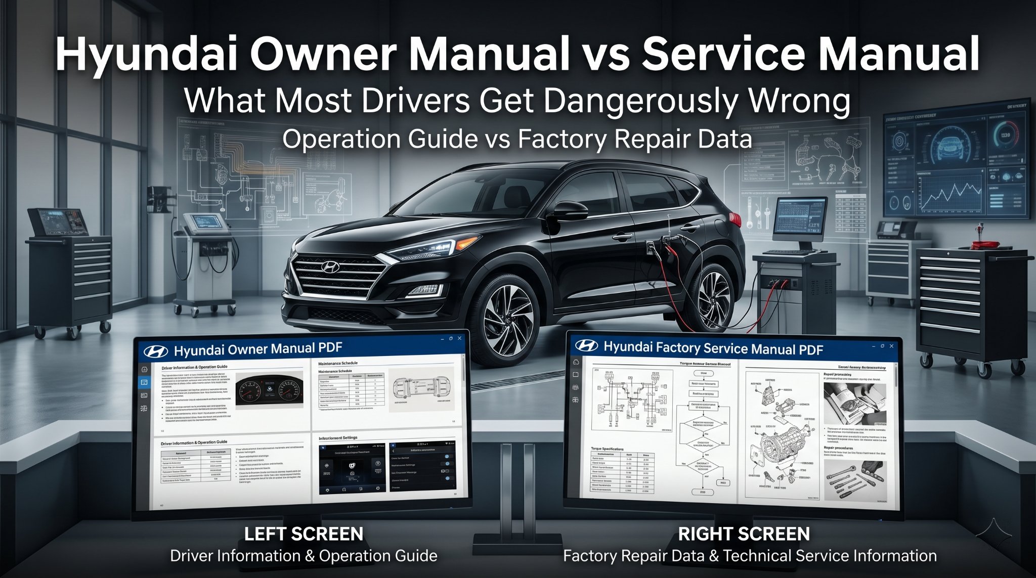
The Owner’s Manual is a consumer guide for vehicle operation and maintenance, while the Service Manual is a technical resource for repairs, diagnostics, and teardowns.

This article breaks down exactly what each manual covers, when to use one over the other, and how to pick the right document for your specific Hyundai model and situation.

Hyundai Owner Manual vs Service Manual: The Truth Most Sites Won’t Tell You

Two types of Hyundai manuals displayed side-by-side on a professional desk

Most comparison articles treat these two documents as similar resources with slight differences. They are not. They serve completely different purposes, have different technical depth, and target entirely different users.

The Hyundai owner manual is written for the everyday driver. The Hyundai service manual is written for technicians or serious DIY mechanics. Confusing the two wastes time and, in some cases, risks real damage to your vehicle.

What a Hyundai Owner Manual Actually Covers

Many drivers assume the owner manual is all they need. It is a good starting point, but its scope is deliberately limited to keep things accessible for general audiences.

A Hyundai owner manual typically includes:

  • Dashboard warning lights and what each symbol means
  • Fluid check locations with basic top-up guidance
  • Recommended maintenance intervals (oil, filters, tires)
  • Infotainment and ADAS feature explanations, such as Lane Keeping Assist and Smart Cruise Control
  • Tire pressure tables and load ratings
  • Fuse box diagrams with fuse ratings
  • Safety and recall notices relevant to your model year

What it does not include is step-by-step repair instructions, factory torque specifications, wiring diagrams, or diagnostic trouble code breakdowns. Those live in the service manual.

If you drive a 2018 Elantra or a 2024 Tucson, your owner manual runs between 400 and 500 pages. It covers roughly 75 labeled components with color diagrams.

Fluid specs list volume in liters and quarts with viscosity grades. It is thorough for general use. But the moment a repair is needed, it stops being useful.

If you need to find a vehicle-specific manual based on your VIN, this vehicle-specific manual lookup can point you in the right direction before you even open either document.

Close-up of a digital Hyundai service manual showing technical wiring diagrams in a repair shop

What a Hyundai Service Manual Actually Contains

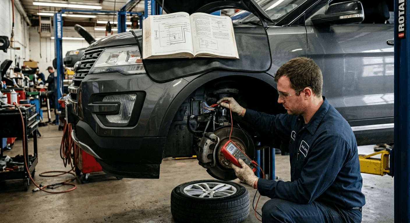
The Hyundai service manual, sometimes called a workshop manual or factory service manual, is a technical document built for repairs. This is the exact same documentation that dealer technicians reference when your car goes in for a scheduled or unscheduled service.

A Hyundai service manual typically includes:

  • Step-by-step repair procedures for every major system
  • Factory torque specifications down to individual fasteners
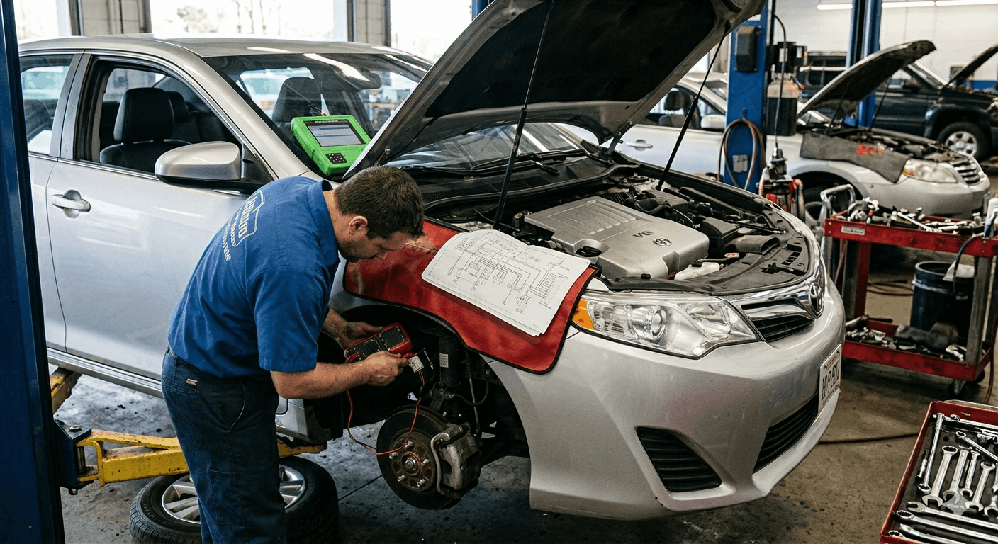
  • Wiring diagrams and connector pin-outs for electrical diagnostics
  • OBD2 diagnostic trouble code charts with flowcharts
  • Engine, transmission, and suspension disassembly and reassembly sequences
  • Hybrid battery diagnostics for applicable models like the Sonata Hybrid
  • Maintenance schedules tied to specific mileage and time thresholds
  • Fluid capacities with exact part numbers for OEM filters and seals

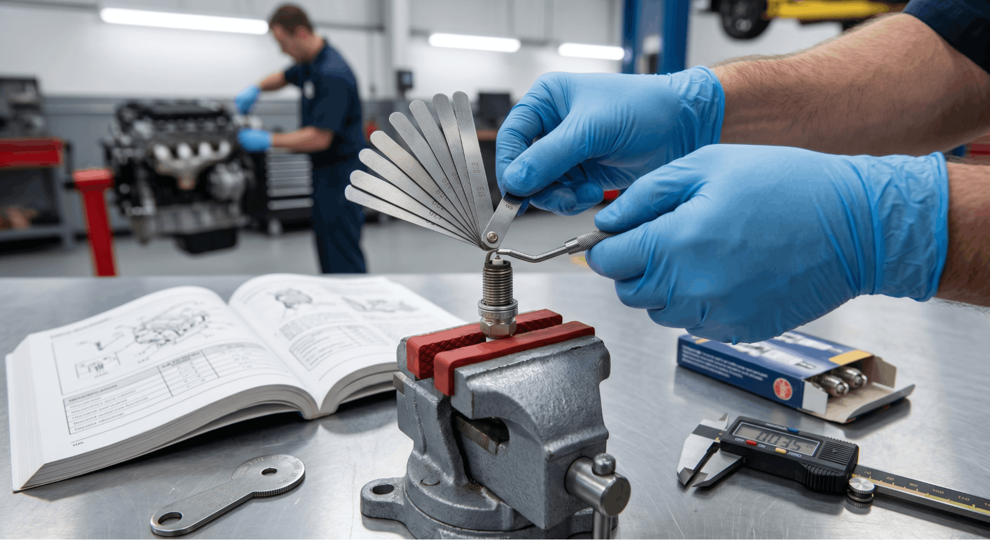
The level of detail is not comparable to an owner’s manual. Where an owner manual says “check coolant level,” a service manual walks you through pressure testing the cooling system, identifying leak points, and specifying the exact torque for the expansion tank cap.

For anyone serious about DIY repairs, a proper Hyundai service manual can significantly reduce repair time and parts costs by avoiding trial-and-error replacements.

Visual representation of using manuals for feature operation versus mechanical repair

Side-by-Side: Owner Manual vs Service Manual at a Glance

Feature Owner Manual Service Manual
Target User Everyday driver DIY mechanic/technician
Repair Instructions None Full step-by-step
Torque Specifications None Complete factory specs
Wiring Diagrams Basic fuse map only Full electrical schematics
Diagnostic Trouble Codes Warning light descriptions OBD2 flowcharts
Maintenance Schedules General intervals Mileage-based detail
Length 400-500 pages typical 1,000+ pages typical
Technical Depth Low High
Use Case Daily operation reference Repair and diagnostics

When to Use the Owner Manual vs Service Manual

Knowing which document to open first saves real time. Here is a practical breakdown by situation.

Use the owner manual when:

  • A dashboard warning light appears, and you want to know what it means
  • You need to confirm the correct tire pressure before a long trip
  • You are checking recommended oil type or change interval
  • You want to understand how a feature like adaptive cruise or park assist works
  • You need to locate a fuse for a non-working accessory

Use the service manual when:

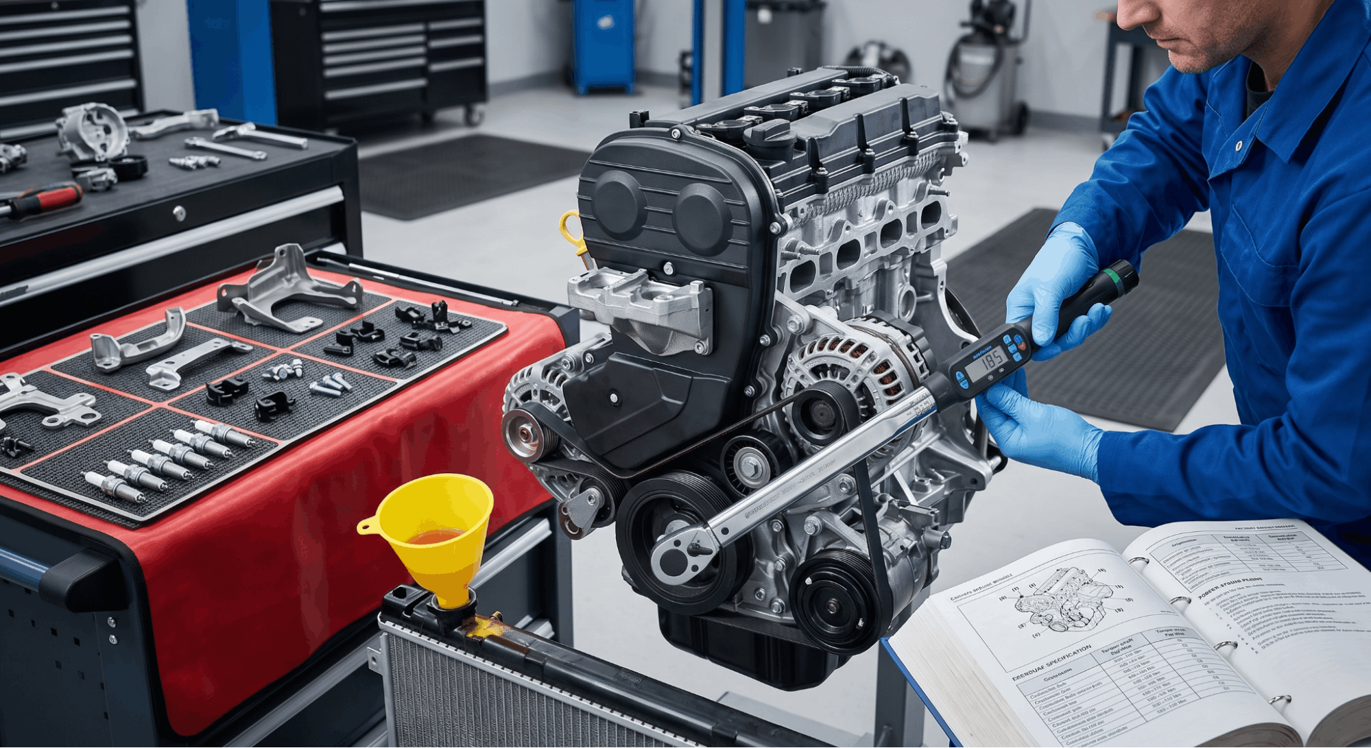
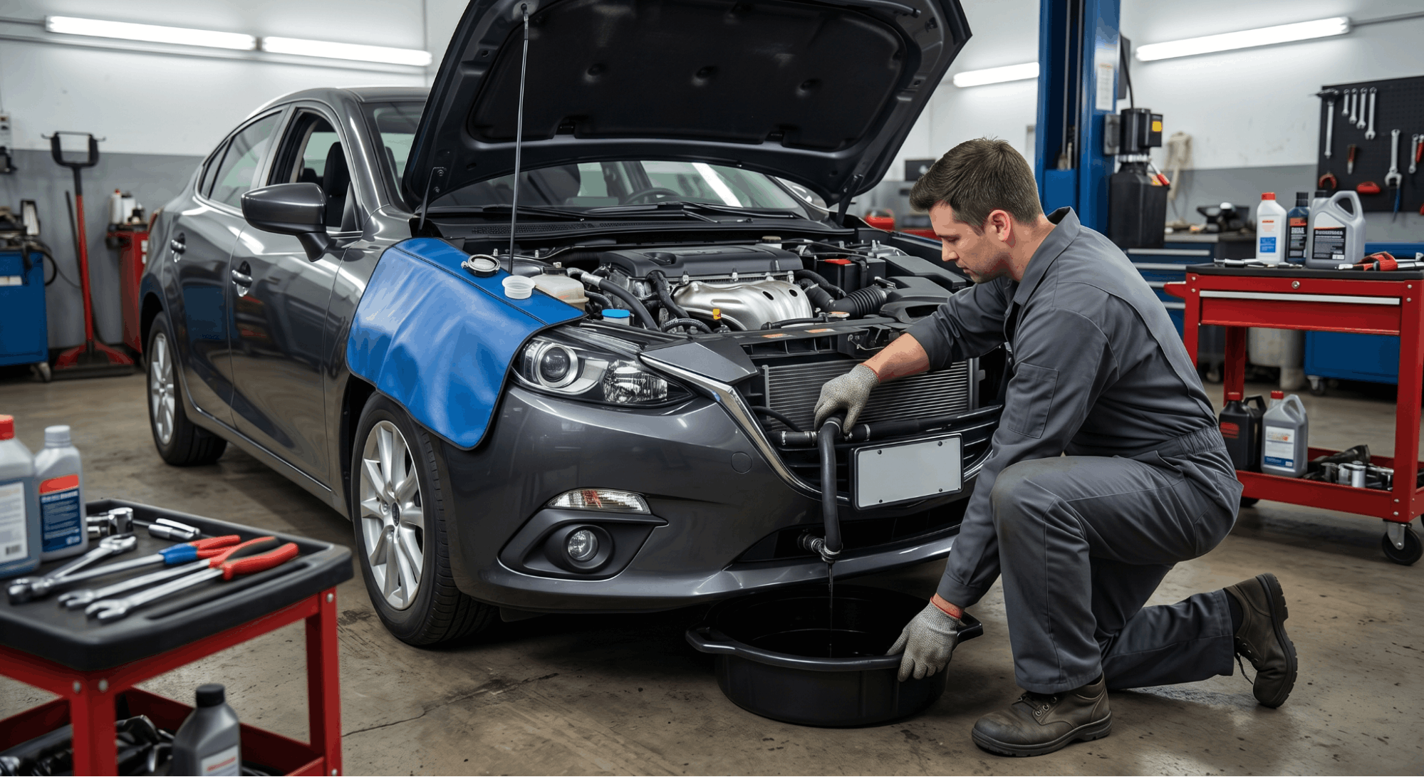
  • You are performing an oil change and need the drain plug torque spec
  • A Check Engine light has triggered, and you want to diagnose the exact code
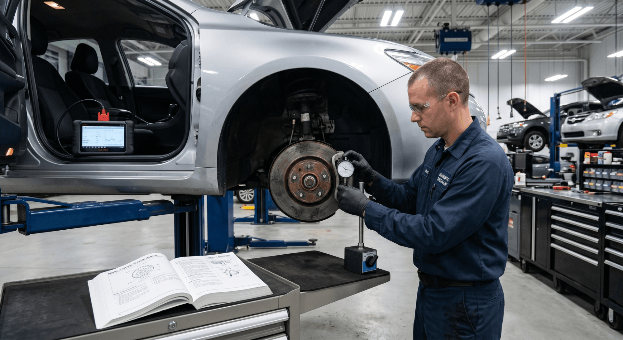
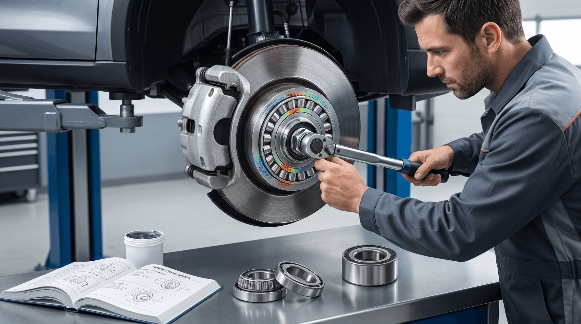
  • You are replacing brake pads, rotors, calipers, or suspension components
  • You are working on the electrical system and need connector pin-out data
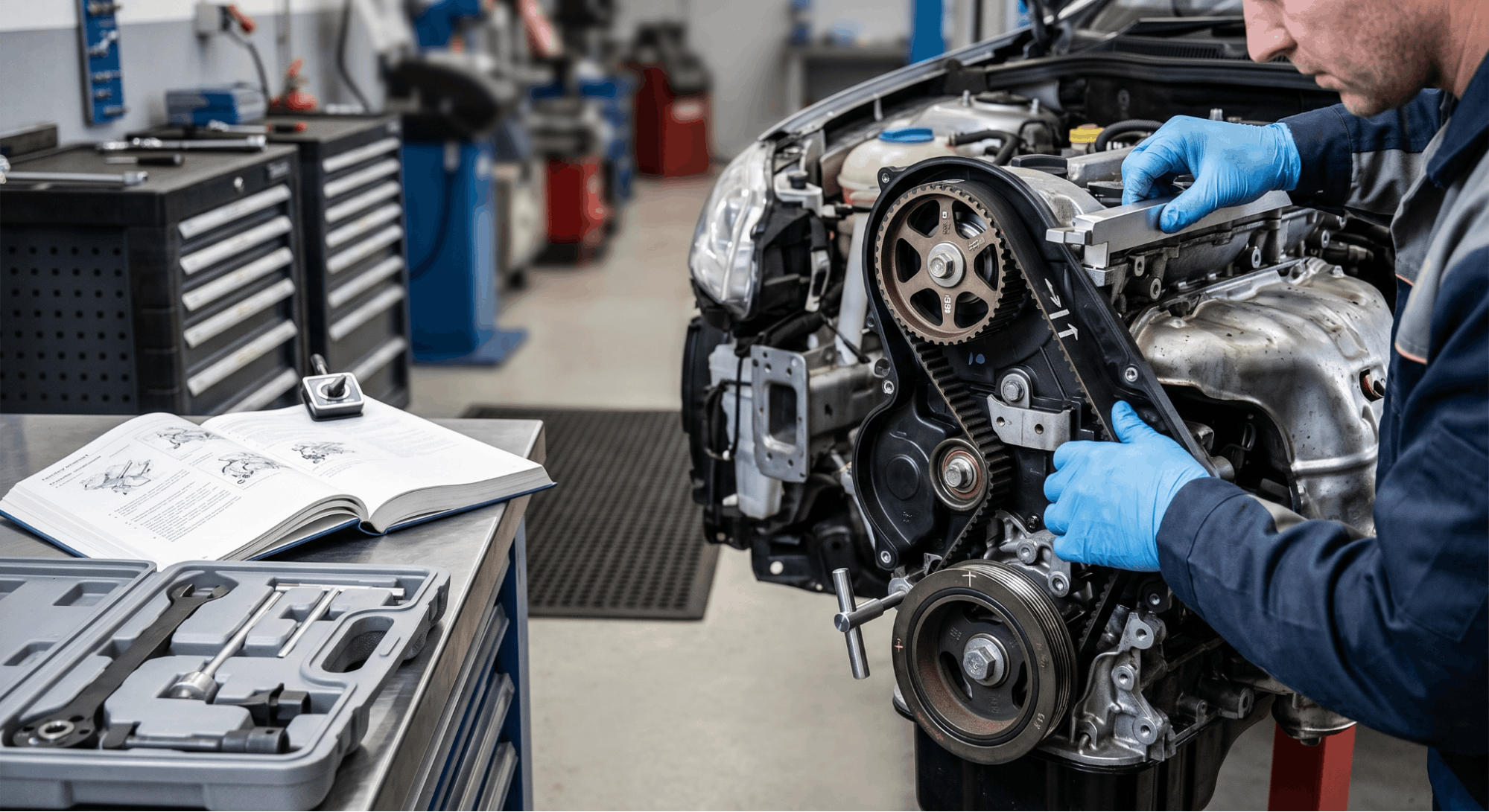
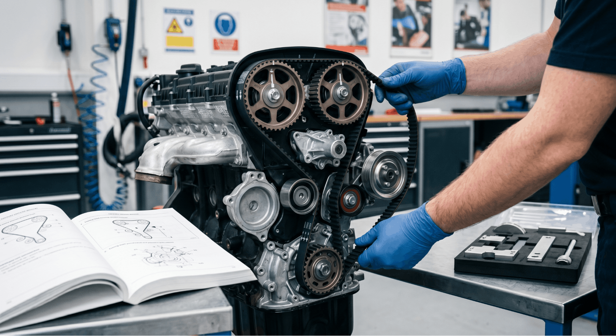
  • You want to replace a sensor, gasket, or timing component correctly

If you are still deciding which document best suits your repair goal, this Hyundai repair manual selection guide clearly lays out the decision-making process. And if you are comparing OEM factory manuals with aftermarket options, this breakdown of how to choose the right repair documentation is worth reading before you commit to a purchase.

A laptop showing a website for downloading official Hyundai service manuals

Where to Find a Genuine Hyundai Service Manual

Sourcing the right manual matters. A mismatched or outdated document can give you incorrect torque specs or obsolete wiring data, which creates more problems than it solves.

Reliable sources for a genuine Hyundai service manual include:

  • Hyundai’s official dealer portal for factory-level documentation
  • Verified digital manual providers that supply model-year-specific PDFs
  • Haynes and Chilton manuals for a more reader-friendly alternative
  • eManualOnline and FactoryManuals for instant downloadable access

Always verify the manual matches your exact model year, trim level, and engine variant. A 2.0L Elantra and a 2.0T Elantra N use different torque specs for shared components. Using the wrong spec is not a minor issue.

For trusted sources of official workshop manual documentation, this guide covers verified options. If you are buying for the first time, this workshop manual buying guide can help you avoid common purchasing mistakes.

A stripped bolt head next to an incorrect repair manual, illustrating common DIY mistakes

Common Mistakes Hyundai Owners Make With Manuals

These errors come up repeatedly in forums, repair communities, and shop discussions. Avoiding them saves time and money.

  • Using only the owner’s manual for repairs. It was not designed for that. Missing torque specs cause stripped threads and failed gaskets.
  • Downloading a manual for the wrong model year. Hyundai updates specifications between model years, sometimes significantly.
  • Confusing a workshop manual with a parts catalog. A parts catalog shows what fits. A service manual shows how to install it correctly.
  • Skipping electrical diagnostics sections. Modern Hyundai vehicles have complex CAN bus systems. Guessing at wiring causes expensive ECU damage.
  • Relying on generic third-party repair guides. These often carry incorrect or incomplete specs for Hyundai-specific components.

Conclusion

The Hyundai owner manual and the Hyundai service manual are not interchangeable. One is for operating your vehicle. The other is for repairing it. Using the right document for the right job is not optional if you want accurate results.

For basic questions about dashboard warnings, fluid checks, or feature operation, the owner manual is exactly what you need. The moment a real repair or diagnostic task begins, the service manual becomes the only document worth trusting.

Identify your task first. Then reach for the correct manual. That single habit will save you time, money, and a lot of unnecessary frustration in the driveway.

Common Asked Questions About Hyundai Owner Manual vs Service Manual

Can I use a Hyundai owner manual to do my own oil change?

The owner manual will tell you the correct oil grade, capacity in liters or quarts, and the recommended change interval for your model. However, it will not provide the drain plug torque specification or the filter tightening sequence.

For a proper DIY oil change, you need to cross-reference the service manual for those mechanical specs. Using the wrong torque on a drain plug is one of the most common causes of stripped threads on Hyundai aluminum oil pans.

The owner’s manual is a starting point for confirming the oil type, but the service manual completes the job safely and correctly.

Is a Hyundai factory service manual the same as a workshop manual?

Yes, these terms are used interchangeably in most contexts. A factory service manual is documentation produced by Hyundai or under OEM authorization for dealership technicians’ use.

A workshop manual is typically a technical document, sometimes produced by a third party like Haynes, that covers similar repair content in a more DIY-friendly format. The factory version uses OEM part numbers and exact specifications.

Third-party workshop manuals are often structured for easier reading but may not always match the OEM level of detail. For complex repairs or electrical work, the factory version is generally preferred.

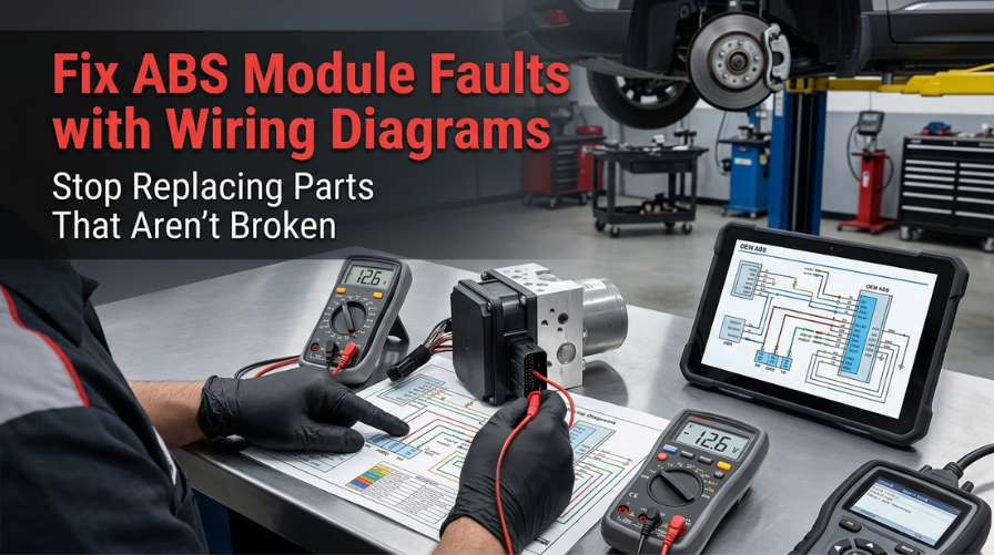
Do Hyundai service manuals cover the electrical system and OBD2 codes?

Yes, a proper Hyundai service manual includes full wiring schematics, connector pin-out diagrams, and OBD2 diagnostic trouble code flowcharts for covered systems. This is one of the biggest gaps between the owner manual and the service manual.

The owner manual only identifies what a warning light means in general terms. The service manual tells you which sensor triggered the code, how to test it, what the voltage range should be, and when to replace it. For electrical diagnostics on models like the Sonata Hybrid or Ioniq PHEV, this section of the service manual is especially critical.

How do I know if my Hyundai service manual matches my exact trim level?

Always cross-check the manual against your vehicle’s VIN, model year, engine code, and trim designation before starting any repair. Hyundai produces different spec pages for the 1.6T, 2.0, and 2.5T engines even within the same model generation.

A service manual downloaded for a base Elantra may not carry the correct torque specs or wiring data for an N-Line or N variant. Most reputable providers allow you to filter by VIN or engine code.

If you are uncertain, the vehicle-specific manual lookup tool is a reliable way to match the correct documentation to your exact vehicle.

Is it worth buying both an owner manual and a service manual for my Hyundai?

For most Hyundai owners who handle even basic DIY maintenance, keeping both documents on hand is genuinely useful. The owner manual handles quick daily-use questions fast. The service manual provides the technical depth needed when actual work begins.

Many experienced DIY mechanics keep the owner manual in the glove box for quick fuse or feature lookups and store the service manual digitally for repair sessions.

The upfront cost of a quality service manual is typically recovered in the first repair, helping you avoid a single dealership labor charge. For anyone doing more than basic fluid top-ups, the investment makes clear practical sense.

Posted on

Timing Belt Replacement Assembly Sequencing: The Exact Order That Saves Your Engine

Mechanic aligning timing belt in engine bay showing precise assembly sequencing steps

Timing belt replacement assembly sequencing is the one thing most DIYers get wrong, and the consequences hit hard. A single step out of order can bend valves, destroy pistons, and turn a $300 job into a $3,000 engine rebuild.

Precise assembly sequencing ensures synchronization and prevents damage. The correct procedure requires setting Top Dead Center (TDC), locking the camshaft and crankshaft before belt removal, and starting the new belt installation at the crankshaft sprocket. Errors typically occur in these critical nuances rather than in basic parts swaps.

This guide walks through the full assembly sequence step by step, covering timing marks, tensioner setup, torque specs, and what to double-check before you button everything back up.

Timing Belt Replacement Assembly Sequencing: Why Order Controls Everything

technician comparing mechanical parts to exploded diagram on workshop bench

Most timing belt jobs fail not because of bad parts, but because of a bad sequence. Getting the order right is the difference between an engine that starts clean and one that never runs again.

This section covers the full assembly sequencing process from the moment you pull the old belt off to the final rotation check. Every step matters, and the order is non-negotiable, especially on interference engines.

Step 1: Set the Engine to TDC Before Touching the Belt

Before anything comes off, you need the engine locked at Top Dead Center (TDC) on cylinder number one’s compression stroke. This is the foundation of the entire replacement job.

Rotate the crankshaft clockwise using a breaker bar on the crankshaft pulley bolt. Watch the timing mark on the crankshaft sprocket and align it to the pointer on the oil pump or block, depending on your engine. At the same time, the camshaft sprocket marks should align with their reference points on the rear timing cover or cylinder head.

  • Rotate the engine by hand, never with the starter motor
  • Confirm both cam and crank marks are aligned before proceeding
  • On DOHC engines, both camshaft sprockets must be aligned simultaneously
  • Use a paint marker to highlight the timing marks for better visibility

If the marks are even slightly off when you start removing the belt, you’re already working out of sequence. Stop and correct it first.

Step 2: Lock the Camshaft and Crankshaft in Position

technician locking camshaft and crankshaft during timing belt service

Once TDC is confirmed, lock everything in place. Most OEM factory service manuals specify a camshaft locking tool that slots into the back of the cam. Without it, any small rotation while the belt is off can cause valve and piston contact on interference engines.

If you don’t have the factory locking tool, you can use a flat bar resting across the camshaft sprocket against a solid reference, but this is not recommended for precision work. The OEM method is always safer.

  • Insert the cam locking bar into the slot at the rear of the camshaft
  • Insert the crankshaft locking pin through the block hole to hold the crank
  • Do not rotate either the camshaft or crankshaft with the belt removed
  • Mark the old belt’s rotation direction with a marker before removal

Locking prevents the engine from rotating due to spring tension from open valves. This step is short, but skipping it is one of the most common causes of botched timing belt jobs.

Step 3: Release Tensioner and Remove the Old Belt

With the engine locked, you can now release the tensioner. Loosen the tensioner pulley bolt approximately half a turn to allow it to pivot and release pressure from the belt. On engines with an auto-tensioner, you’ll need to compress the hydraulic piston and hold it with a locking pin.

Slide the belt off the sprockets in this order: tensioner pulley first, then idler, then camshaft sprockets, then crankshaft sprocket last. Never pry the belt off with a screwdriver. Forcing it can damage the pulley teeth and crack the tensile cords inside.

  • Loosen, do not remove, the tensioner bolt to release belt slack
  • Slide the belt off without prying or forcing
  • Inspect the old belt for unusual wear patterns, cracking, or missing teeth
  • Note any oil or coolant contamination, which signals a seal leak to fix before installing the new belt

This is also the right time to check the water pump for shaft play or bearing noise. Replacing it now, while the assembly is open, saves significant labor later. Many experienced techs also swap the idler pulley and tensioner pulley at this point, regardless of their condition.

Step 4: Inspect and Prepare Before Installing the New Belt

You should never rush to install the new belt immediately after pulling the old one. Take a few minutes to inspect everything within the timing assembly before the new belt goes on.

Check the crankshaft seal and camshaft seals for any oil weeping. A new timing belt running in contaminated oil will fail well before its normal lifespan. If the seals look questionable, replace them now. Clean the sprocket faces and housing area thoroughly.

Component to Inspect

What to Look For

Replace If

Camshaft Seals

Oil seepage or weeping

Any visible leak

Crankshaft Seal

Oil contamination around the sprocket

The belt shows oil residue

Water Pump

Shaft play, bearing noise, and leak

Any of these present

Tensioner Pulley

Rough bearing feel, wobble

The bearing feels rough

Idler Pulley

Bearing noise or play

Any roughness felt

You can find a comprehensive breakdown of how to verify drive belt tension specs in OEM manuals, including the steps for checking factory tolerances prior to the last tensioning stage, at the following link.

Step 5: Route and Install the New Belt in the Correct Sequence

technician routing timing belt through crank and cam sprockets during installation

Here is where the assembly sequencing truly matters most. The routing order is not optional. Install the new timing belt in this exact sequence:

  1. Crankshaft sprocket first keep the tension side of the belt taut
  2. The front or intake camshaft sprocket maintains tension as you route upward
  3. Water pump pulley (if belt-driven)
  4. Idler pulley
  5. Tensioner pulley last do not tighten yet

This sequencing keeps the belt slack concentrated on the tensioner side, exactly where it belongs. Starting at any other sprocket disrupts alignment and creates uneven slack, pulling timing marks out of position.

  • Never force or stretch the belt during installation
  • Confirm the front face of the belt (marked with arrows) faces the correct direction
  • Keep constant light tension on the loaded side of the belt as you route it
  • Do not let the belt drop below the sprocket grooves at any point during routing

If your engine has balance shaft sprockets, route those in between the cam and crank steps per your factory service manual. These vary by engine, and skipping them causes vibration and noise even if the main timing marks look correct.

Step 6: Set Tensioner and Verify Timing Marks

Once the belt is routed, it is time to set the tensioner. For spring-loaded tensioners, simply loosen the tensioner bolt and allow the spring to push it against the belt. For auto-tensioners, remove the locking pin and let the hydraulic pressure set itself.

Torque the tensioner bolt to the OEM specification for your engine. Do not guess at this. Using incorrect torque either over-tensions the belt (causing premature wear on the belt and bearings) or leaves it too loose (causing slip and timing error).

  • Torque the tensioner pulley bolt to spec, typically in the 30 to 43 ft-lb range, depending on the engine
  • Verify the belt can be twisted approximately 90 degrees at the longest free span
  • Confirm all timing marks on the cam and crank sprockets are still aligned
  • Rotate the crankshaft by hand two full clockwise turns and stop at TDC

After two full rotations, stop at TDC and recheck every timing mark. They must all realign perfectly. If any mark is off by even one tooth, remove the belt and restart the installation sequence. One tooth off on a DOHC engine can result in valve contact at startup.

For understanding how torque values apply to related engine work, see this detailed guide on engine torque specs for cylinder heads.

Step 7: Reassemble in Reverse Order and Final Check

technician torquing crankshaft pulley during engine reassembly after timing belt service

With timing confirmed, reassemble the engine in reverse of the disassembly sequence. Install the lower timing cover first, then the crankshaft pulley, then the upper timing cover. Torque the crankshaft pulley bolt to the high specification listed in your service manual. This bolt typically requires 80 to 120 ft-lb of torque, depending on the engine.

Reinstall the serpentine belt and any removed accessory belts. Reconnect anything that was removed for access: the motor mount, if applicable, the power steering pump, the alternator bracket, and any wiring harness clips.

  • Reinstall spark plugs if they were removed for engine rotation
  • Refill the coolant if the water pump was replaced
  • Start the engine and listen for any squealing, ticking, or unusual rhythm from the timing cover area
  • Perform a final idle check and scan for any fault codes

To verify your specific assembly diagrams and torque specifications, you may need to find the appropriate factory service manual PDF by VIN, a procedure detailed at.

Common Sequencing Mistakes That Cost Real Money

Even experienced mechanics make sequencing errors when rushing a timing belt job. These are the ones that come up most often.

Mistake

Consequence

Skipping TDC confirmation

Timing marks are misaligned from the start

Not locking cams before belt removal

Cam rotates from spring tension

The routing belt starts at the cam instead of the crank

Uneven slack, alignment error

Releasing the tensioner before routing is complete

Belt slips off sprocket mid-install

Skipping the two-rotation verification

Misaligned belt installed without knowing

Ignoring oil contamination on pulleys

New belt fails prematurely

Consulting your valve clearance tolerances is crucial during this procedure, especially if the cylinder head has been removed or seals are being swapped. Ensuring these specifications are cross-referenced with your official factory manual is a vital step in the process.

Conclusion

Getting timing belt replacement assembly sequencing right comes down to one principle: respect the order. Every step builds on the one before it, and every shortcut compounds into a larger problem.

Start at TDC, lock your cams and crank, remove the old belt without prying, inspect everything before the new belt goes on, route from the crankshaft sprocket first, tension last, and always verify with two full rotations before buttoning it up.

This is not a job that rewards speed. It rewards patience and precision. Get the sequence right, and the engine will run cleanly for another 60,000 to 100,000 miles. Get it wrong, and you are looking at a parts list that makes the timing belt cost look like pocket change.

Acquiring authentic OEM workshop manuals is the most critical preparatory step if you lack the official documentation for your engine. This essential resource can be accessed at.

Frequently Asked Questions

Yes, it does differ. On a SOHC engine, you are aligning one camshaft sprocket and one crankshaft sprocket, which simplifies the routing order slightly. On a DOHC engine, both camshaft sprockets must be locked and aligned simultaneously before the belt is routed. 

Skipping one cam alignment on a DOHC engine will cause the belt to be off by multiple teeth even if the crank mark looks correct. Always follow the specific routing diagram in your OEM service manual, since even two DOHC engines from the same manufacturer can have different belt routing paths depending on whether a balance shaft or auxiliary sprocket is involved.

Installing the timing belt one tooth off shifts the valve timing, which means valves open and close at the wrong point in the engine cycle. On a non-interference engine, this causes rough idle, misfires, and poor fuel economy, but the engine can still run. 

On an interference engine, even one tooth of misalignment can result in piston-to-valve contact at startup, causing bent valves and potential piston damage. This is why the two-rotation hand-turn verification after installation is not optional. It is the only way to catch a one-tooth error before the engine starts.

Most professional mechanics and OEM documentation strongly recommend replacing the water pump at the same time as the timing belt, especially if the water pump is belt-driven. 

The water pump works at the same load intervals as the belt and typically has a similar service life. Labor cost is the main reason to do both together, since the pump is accessible when the timing covers are already off.

Installing a new belt on an old pump that fails a few months later means tearing the entire assembly apart again. Replacing it proactively is cheaper in the long run and prevents unexpected coolant failure.

Proper tensioning depends on the tensioner type. For spring-loaded tensioners, loosen the tensioner bolt to allow the spring to automatically apply the correct force, then torque the bolt to spec.

For manual tensioners, set the belt deflection by applying a measured force at the center of the longest belt span and adjusting until it matches the OEM value, typically around 0.5 inches.

For hydraulic auto-tensioners, releasing the locking pin allows the hydraulic piston to expand and self-set tension. After setting, rotate the engine two full turns and recheck. If the belt can be twisted more than 90 degrees at the longest span, it is too loose.

Technically, you can reuse a timing belt that shows no visible cracking, missing teeth, glazing, or oil contamination, but most experienced mechanics advise against it.

Once a timing belt is removed, it loses its break-in seating on the sprockets, and the internal fiber cords may have micro-stress that is not visible externally. 

The cost of a new belt is minor compared to the labor involved in the job. More importantly, the belt’s remaining service interval becomes completely unknown after it is removed and reinstalled. 

If the belt is anywhere near its replacement mileage, there is no justification for reusing it.

Posted on

Drive Belt Tension Specs in OEM Manuals: What Most Mechanics Get Dangerously Wrong

Technician measuring serpentine belt tension using OEM factory specifications

Using non-OEM drive belt tension specifications can cause engine damage by overloading bearings and seals. Precise factory values are essential to prevent component failure.

Technicians must use OEM-sourced tension values for reliable repairs. Standards vary, utilizing gauges or deflection ratios to achieve the minimum tension required to stop slippage.

This article covers how OEM manuals present belt tension specs, which measurement methods apply to which vehicles, and where experienced technicians still make costly errors.

Drive Belt Tension Specs in OEM Manuals: The Data Most Guides Quietly Skip

technician measuring brake rotor runout while diagnosing ABS system issue

OEM manuals list engine-specific belt-tension values that no aftermarket guide can replicate with full accuracy. Each manufacturer calibrates these specs based on belt composition, pulley diameter ratios, accessory load, and operating temperature range. 

Pulling values from a generic chart, even one that looks detailed, almost always means using data mapped to a different configuration. Understanding how factory documentation formats this data is what separates a correct repair from one that fails quietly over the next 10,000 miles.

Why OEM Tension Specs Differ Across Engine Families

Not every engine uses the same belt routing or accessory load, which is why specs vary even across trims of the same model year.

The drive system on a 2.0L inline-four behaves entirely differently from a 3.5L V6, even on the same platform. OEM manuals define tension values based on controlled testing under specific load conditions that no third party replicates. That is data that no aftermarket repair guide can carry with real accuracy.

Key variables that OEM engineers account for individually include:

  • Belt width and rib count (4PK vs. 6PK configurations)
  • Number of driven accessories (A/C compressor, power steering pump, water pump)
  • Pulley diameter and wrap angle at each contact point
  • Operating temperature range within the engine bay
  • Belt material composition (EPDM compounds vs. older neoprene)

If sourcing documentation, a genuine OEM workshop manual will carry these values listed with part-specific precision that generic charts simply cannot match.

How OEM Manuals Present Belt Tension Data

Factory documentation does not always present belt tension specs in the same format, and misreading that format is among the most common errors in drive belt service.

Some OEM manuals list tension in Newtons (N) for new belts and a separate lower range for used belts. Others list deflection in millimeters at a specific midpoint load, and a growing number have shifted to frequency-based measurement in Hertz using a sonic tension meter. 

Knowing which method the manual specifies changes the tool you reach for before anything else.

Format Type

Unit Used

Measurement Method

Load-Deflection

mm at specified kg force

Push at the belt midpoint

Tension Force

Newtons (N)

Tension gauge on the belt

Frequency (Sonic)

Hertz (Hz)

Sonic tension meter

Auto-Tensioner

Visual indicator

Tensioner window mark

Reading the wrong column, such as using new-belt specs on a used belt, results in overtightening that damages bearing races. Always check if the manual separates initial installation values from re-tensioning values after break-in.

Deflection vs. Frequency: Which OEM Spec Method Applies

technician measuring drive belt tension using deflection gauge and sonic meter

The method your OEM manual specifies determines the tool required and the accuracy of the final result.

Deflection-based specs require applying a known load at the belt’s longest free span and measuring the resulting inward deflection. 

Frequency-based specs use a sonic tension meter placed near the belt to detect vibration frequency, which directly correlates with the actual tension in the system. Both are valid methods. They are not interchangeable under any circumstances.

Confirm the right approach before measuring:

  • Check the spec table header in the OEM manual for the unit listed
  • Confirm the free-span length referenced, as the measurement point directly affects the result
  • Note if values differ for new vs. used belt condition
  • Verify if the manual requires the engine to be running or cold during measurement
  • Match your tool (deflection gauge vs. sonic meter) to the format listed in the manual

Incorrect method selection is one of the most frequently overlooked errors in drive belt service, and it is entirely avoidable with one careful read of the factory documentation.

Reading OEM Tension Tables Without Making Costly Errors

Reading OEM Tension Tables Without Making Costly Errors

OEM tension spec tables contain multiple data points, and missing even one of them creates a downstream problem.

Most technicians scan only for the tension value and miss the measurement conditions printed directly above or beside it. The engine temperature at the time of measurement, the specific belt span to test, and the belt condition all affect which number applies. 

If the vehicle’s manual is not on hand, a factory service manual PDF by VIN provides the exact documentation for that specific engine code.

Common errors when reading belt tension tables:

  • Using the spec for a different engine variant listed on the same page
  • Confusing the measurement span with the total belt length
  • Applying new-belt tension values to a belt with over 20,000 miles of use
  • Ignoring the ambient temperature note printed in the manual footnote
  • Misidentifying which belt the table references (serpentine vs. accessory vs. timing)

An overtightened belt causes bearing failure in the alternator or A/C compressor over time. An under-tensioned belt slips under load, generates significant heat, and wears through faster than most expect.

OEM Spec Formats by Manufacturer: A Practical Reference

Manufacturer Group

Preferred Spec Method

Typical Tension Range

Key Note

Japanese OEMs (Toyota, Honda)

Deflection (mm)

7-12 mm at 10 kg force

Separate new/used values in the table

German OEMs (BMW, VW)

Frequency (Hz)

100-180 Hz

Sonic meter required

American OEMs (Ford, GM)

Auto-tensioner indicator

Visual window mark

No manual measurement needed

Korean OEMs (Hyundai, Kia)

Deflection or force (N)

400-700 N

Varies by engine family

This table reflects general patterns across manufacturer groups. Always verify with your specific OEM manual for your exact engine code before proceeding. General patterns do not replace model-specific data.

When Incorrect Belt Tension Triggers Bigger System Failures

A belt running outside its specified tension range does not just wear faster. It stresses every component it drives.

Bearings in the alternator and power steering pump are designed for a precise side-load. When belt tension exceeds that limit, those bearings fail ahead of schedule, often taking the housing with them. On cooling-dependent systems, a slipping belt can reduce water pump output enough to contribute to car overheating under sustained load.

Other precision values, such as valve clearance tolerances in factory manuals, follow the same format sensitivity as belt tension specs. The engine is a system. Each spec supports the ones around it. Pulling one value incorrectly creates a chain of problems that only appear later.

Conclusion

Drive belt tension specs from OEM manuals are engineered limits, not loose guidelines. The format, the measurement method, and the condition-specific values all carry equal weight in the outcome. 

Matching the right tool to the right method and pulling data from the right source keeps the entire drive system within design limits.

Frequently Asked Questions

No, and this distinction is one that OEM manuals address with a dedicated column in the spec table. A new belt stretches slightly during its first hours of operation, which is exactly why manufacturers publish separate tension values for initial installation and re-tensioning after break-in. 

Applying new-belt specs to a belt with significant mileage results in overtightening, which adds damaging side-load to the accessory bearings. The difference in values can reach 100 N or 2-3 mm of deflection, depending on the manufacturer. 

That gap is not negligible in service, and it is the reason OEM documentation separates the two conditions.

It depends entirely on the manufacturer group. Japanese and Korean OEM manuals typically use millimeter deflection or Newtons of force as the primary spec unit. German manufacturers often specify frequency in Hertz, which requires a sonic tension meter to measure accurately. 

American OEMs increasingly rely on automatic tensioners with visual indicator windows, removing manual measurement from the process entirely. The unit listed at the top of the spec table in your factory documentation tells you exactly which measurement tool applies to that job. 

Using a deflection gauge against a frequency-based spec produces a result that looks valid but is not.

A factory service manual PDF by VIN is the most direct path to your exact OEM documentation. Manufacturer and dealer portals also host these files, though subscription access may be required for full document retrieval. Avoid pulling specs from general repair databases unless you can confirm the data source is the original manufacturer file. 

Third-party aggregators sometimes carry outdated or misattributed values from older revisions. Your engine code, not just the vehicle model name, must match the spec table you reference. A mismatch at that level produces an incorrect result regardless of how carefully the measurement is taken.

Yes, in cases where the OEM manual includes a temperature condition for measurement. Some manufacturers specify that tension measurements must be taken with the engine completely cold. Others require measurement after the engine has reached full operating temperature. 

Belt material expands slightly with heat, and effective tension at operating temperature differs from a cold reading. Ignoring the temperature condition listed in the spec footnote produces a reading that does not reflect real-world operating tension

Always identify and replicate those conditions before testing. This detail is printed alongside the spec table in most factory documentation and is easy to miss when scanning quickly.

Most manufacturers recommend verifying belt tension at every major service interval, typically every 30,000 to 60,000 miles, depending on the platform. Any service involving tensioner replacement, accessory removal, or belt replacement resets that interval, and tension must be confirmed immediately after reinstallation using the new-belt values from the OEM manual

Some factory documentation also specifies a follow-up check after the first 500 to 1,000 miles following a new belt installation, as initial stretch during break-in can drop tension below the acceptable minimum. Confirming both the installation value and the break-in follow-up is the correct two-step process.

Posted on

Brake Rotor Minimum Thickness Specifications: What Every Driver Must Know

Technician measuring brake rotor thickness using micrometer and OEM specifications

Ignoring your brake rotor minimum thickness specifications is one of the most dangerous decisions a driver can make. A rotor that falls below its approved minimum thickness loses its ability to handle heat, putting your entire braking system at risk.

New passenger rotors usually measure 20–30 mm. After 2–3 mm of wear reaches the “MIN TH” limit, replacement is mandatory to avoid brake fade or structural issues. Front rotors generally wear to 10–28 mm, while rears wear to 8–20 mm.

This article covers how to read and locate rotor specifications, what happens when you ignore them, how to measure correctly, and a full reference table for common vehicles.

Brake Rotor Minimum Thickness Specifications: The Exact Numbers You Need

technician comparing refrigerant types and compressor oil compatibility in workshop

Most drivers only think about brake pads when something goes wrong. But the rotor itself wears every time the pads press against it. Over thousands of miles, that friction steadily reduces its thickness below safe limits. 

Understanding the exact minimum thickness specifications for your vehicle’s brake rotors is not complicated. You just need to know where to look and what to do with the numbers.

Common Vehicle Rotor Thickness Reference Table

The values below are general industry references. Always confirm with your vehicle’s service manual or the stamp on the rotor itself.

Vehicle / Category

Rotor Type

Original Thickness (mm)

Min. Thickness (mm)

Compact Sedan (e.g., Honda Civic)

Solid Rear

8 – 10

7 – 8

Compact Sedan (e.g., Honda Civic)

Vented Front

22 – 25

19 – 22

Mid-size Sedan (e.g., Toyota Camry)

Vented Front

28

25.4

Mid-size Sedan (e.g., Toyota Camry)

Solid Rear

10

8

Full-size Truck (e.g., Chevy Silverado)

Vented Front

34 – 36

31 – 33

Full-size Truck (e.g., Chevy Silverado)

Vented Rear

28 – 30

25 – 27

SUV (e.g., Ford Explorer)

Vented Front

30 – 32

27 – 28

Performance Vehicle (e.g., BMW 3 Series)

Vented Front

30 – 32

28

Economy Hatchback

Vented Front

20 – 24

18 – 22

Where to Find the Minimum Thickness Stamp on Your Rotor

Every rotor comes with its minimum thickness cast or stamped directly onto the metal. The tricky part is that road grime, rust, and salt can cover this mark over time.

Here’s where to check:

  • On the outer edge or hub flange of the rotor face
  • Inside the vanes on vented rotors
  • On the hat section near the center bore
  • In the vehicle’s factory service manual or OEM workshop documentation

If the stamp is unreadable, cross-reference with your vehicle’s repair manual. For fast lookup, check a factory service manual PDF by VIN to get the exact OEM spec within seconds.

How to Measure Rotor Thickness the Right Way

technician measuring brake rotor thickness with micrometer in workshop

A visual check is not enough. You need a micrometer, not a regular caliper, to get an accurate reading of the remaining rotor thickness.

Follow these steps carefully:

  • Step 1: Lift and secure the vehicle safely on jack stands.
  • Step 2: Remove the wheel to expose the brake rotor.
  • Step 3: Use a wire brush and brake cleaner to remove surface rust from the measurement area.
  • Step 4: Place the micrometer at the thinnest contact area where pads meet the rotor.
  • Step 5: Measure at 8 to 10 different points around the circumference rotors wear unevenly.
  • Step 6: Record the lowest reading. That is your true minimum point.
  • Step 7: Compare against the stamped minimum specification. A number at or below that means immediate replacement.

One important note: replace rotors in pairs, even if only one side has dropped below spec. Mismatched rotor thicknesses between sides can cause the vehicle to pull during braking.

What Happens When Rotors Drop Below Minimum Thickness

technician resurfacing brake rotor on lathe while measuring thickness

This is not a theoretical risk. Running rotors below their minimum thickness specifications creates a predictable chain of failures, and they tend to build on each other fast.

  • Thermal overload: Thin rotors dissipate heat poorly. Brake fluid can reach temperatures above 200°C, causing vapor lock and complete loss of pedal pressure.
  • Cracking: Reduced metal thickness can’t handle the mechanical stress of hard stops, leading to surface cracks on the braking face.
  • Brake fade: Heat that can’t escape builds up rapidly, reducing friction and braking efficiency exactly when you need it most.
  • Increased pedal travel: As the rotor surface thins, caliper pistons extend further to maintain contact, eventually leading to a spongy or unresponsive pedal.
  • Pad and caliper damage: A worn rotor will destroy new brake pads faster and can score or damage calipers.

If your vehicle shows a brake warning light alongside vibration or pulling under braking, the rotor condition should be checked immediately. Understanding how to isolate hydraulic vs. electronic brake warning light faults can help you distinguish between a sensor fault and an actual mechanical problem.

Discard Thickness vs. Minimum Thickness: Not the Same Thing

Many drivers confuse these two terms, and shops sometimes use them interchangeably, which causes real problems.

Term

Definition

Action Required

Original Thickness

Factory-new rotor measurement

Reference only

Minimum Thickness (MIN TH)

Stamped spec minimum to install new pads

Replace if at or below this number

Discard Thickness

Absolute safety floor for inspection purposes

Immediate replacement, no exceptions

Machining Allowance

Metal removed during resurfacing

Must stay above MIN TH after machining

BMW’s technical service bulletins, for instance, define two separate figures: the stamped MIN TH (used when fitting new pads) and a slightly higher inspection minimum (nominal thickness minus 2.4 mm for standard vehicles). Both matter depending on the situation.

When Can You Resurface a Rotor Instead of Replacing It?

Resurfacing or ‘turning’ a rotor on a brake lathe removes a thin layer of metal to restore a smooth friction surface. It used to be standard practice, but modern vehicles have changed the equation.

You can consider resurfacing only if all of these conditions are met:

  • The rotor is still above the minimum thickness before machining
  • After machining, it will still sit above the discard specification
  • There is no surface cracking, heat bluing, or deep scoring
  • Lateral runout is within manufacturer tolerance (typically under 0.05 mm)

In most cases today, the cost of machining is close to the cost of a new budget rotor. Given that thinner rotors warp faster and dissipate heat worse, replacement is almost always the better call, especially in high-mileage vehicles or those driven in wet, salty conditions.

How Worn Rotors Affect ABS and Electronic Braking Systems

technician measuring brake rotor runout while diagnosing ABS system issue

It’s easy to think of rotor thickness as a purely mechanical concern. But in modern vehicles, thin or warped rotors interact directly with electronic systems.

When a rotor develops uneven wear or thickness variation (DTV), the resulting pulsation can trigger false signals to the ABS module. This can result in ABS activating at low speeds, increased stopping distances, and warning lights that confuse the diagnosis.

If you’re chasing an ABS fault and the mechanical brakes haven’t been inspected, start there first. Detailed guidance on ABS warning light troubleshooting by brake system architecture is available at.

How Often Should You Check Brake Rotor Thickness?

Most manufacturers and technicians agree on a few practical intervals.

  • Every 10,000 to 25,000 miles as a standard inspection interval
  • At every brake pad replacement without exception
  • Immediately, if you feel pedal pulsation, vibration, or pulling when stopping
  • After any aggressive driving event, like mountain driving or emergency braking
  • Before and after winter in high-salt environments where corrosion accelerates wear

As a general rule, front rotors wear faster than rear rotors because the front axle handles the majority of the braking load. Plan your inspection schedule around the fronts.

Final Takeaway: Specifications Exist for a Reason

Brake rotor minimum thickness specifications are not suggestions. They are the line between controlled stopping and a system failure that can’t be undone.

The number stamped on your rotor represents the result of rigorous engineering testing, the point at which heat dissipation, structural strength, and braking performance can no longer be guaranteed.

Check your rotors at every pad change. Measure properly with a micrometer. And when the spec says replace, replace. Getting the right numbers for your specific vehicle starts with knowing where to look, and for that, a genuine OEM workshop manual is always your most reliable source. You can find verified specs at.

Frequently Asked Questions

You can sometimes spot early signs through the wheel spokes using a flashlight. Look for a wear groove or lip at the outer edge of the rotor. If the outer unworn ridge is noticeably raised compared to the swept surface, the rotor has worn significantly.

That said, visual checks are never reliable enough on their own. The only accurate method is to remove the wheel and use a micrometer to measure at multiple points across the friction surface.

Pay particular attention to symptoms like pedal pulsation, vibration through the steering wheel, or a car pulling to one side under braking. Any of these suggests your rotors need to be measured immediately, not at your next service.

Technically, a vehicle may still stop, but the safety margin is gone. Rotors below their minimum specification have reduced heat capacity, which means a single hard stop under load could push the system into brake fade or vapor lock. That’s a scenario where pressing the pedal results in almost no deceleration.

There’s also the risk of the rotor cracking under pressure. A catastrophic crack during braking at highway speed is not a recoverable situation. Mechanics universally advise against operating a vehicle once you know the rotor thickness has dropped below the stamped minimum.

If you’re in a situation where you must drive briefly before repair, avoid aggressive braking, high speeds, and any loaded conditions, such as towing or carrying passengers. But treat this as emergency mode only, not a deferral strategy.

No. Front and rear rotors are engineered differently because they perform different roles. Front rotors handle more braking force, especially during emergency stops, so they are typically larger, vented, and have a higher original thickness, which also means a higher minimum thickness.

Rear rotors on most passenger vehicles are smaller, often solid rather than vented, and have a lower original thickness. Their minimum specification is also sometimes lower, as little as 7–8 mm, compared to a front spec of 19–22 mm on the same vehicle.

Always look up specifications separately for front and rear when doing an inspection. Applying the wrong figure to the wrong axle is a common mistake that leads to either premature replacement or, worse, riding on rotors that should already have been pulled.

The machining minimum is the thinnest a rotor can be after resurfacing and still have enough material for a full service life with new pads. The discard thickness is the absolute safety floor, the point at which the rotor must be removed from service, regardless of surface condition.

In practice, the discard thickness and the MIN TH stamped on the rotor are often the same number or very close. Some manufacturers list an additional ‘inspection minimum’ that sits slightly above the discard figure, specifically for periodic checks.

For vehicles with perforated or cross-drilled rotors, the rules differ. These rotors typically cannot be machined at all, and new pads may only be installed if the current thickness is strictly greater than (not equal to) the MIN TH stamp.

Disc thickness variation (DTV) happens when a rotor wears unevenly, leaving some areas thicker and some thinner around its circumference. As the rotor spins, the brake pads encounter these high and low spots, creating a fluctuating clamping force.

This translates directly into what drivers feel as pedal pulsation or vibration during braking. Even variations as small as 0.02 mm can be felt under certain conditions, especially at highway speeds during light to moderate braking.

DTV often develops not from simple wear but from uneven heat distribution or improper pad bedding after installation. It’s one reason why measuring at 8 to 10 points matters a single-point measurement won’t catch DTV, and a rotor can pass a basic thickness check while still causing pulsation.

Posted on

AC Refrigerant Capacity & Compressor Oil Specs: One Wrong Number Kills Your Compressor Fast

Technician servicing car AC system using refrigerant gauge and OEM specifications

Your AC system’s refrigerant capacity, compressor oil specs, and oil type are not details you estimate they’re the exact numbers that keep a compressor alive or destroy it within a single season. Technicians who skip this step face seized compressors, sky-high repair bills, and unhappy customers before summer even peaks.

Precise matching of refrigerant charge and PAG oil viscosity is mandatory to prevent failure. Systems typically use R134a or R1234yf with specific ISO 46, 100, or 150 PAG oils. Typical capacities range from 14–25 oz of refrigerant and 3–6 oz of oil, but always confirm specs via the under-hood decal.

This guide covers how AC refrigerant capacity is measured, how compressor oil specs are selected by refrigerant type, how oil is distributed across components, and the critical mistakes that cost shops thousands of dollars every year.

AC Refrigerant Capacity & Compressor Oil Specs: The Data That Protects Every Job

calibrating torque wrench using tester in automotive workshop

Understanding AC refrigerant capacity and compressor oil specifications at the technical level separates guesswork from precision. Every vehicle carries a specific refrigerant charge in ounces, along with a matched oil type and viscosity, and both must be correct for the system to perform and last. Getting one wrong cascades into the failure of the other. 

This section walks through every factor, with data and tables to support it.

Most failures trace back to one of two errors: wrong oil type for the refrigerant in use, or wrong total oil quantity during a component replacement. Both are avoidable when you know the specs before you open the system.

Why Refrigerant Type Controls Your Oil Choice

technician comparing refrigerant types and compressor oil compatibility in workshop

The refrigerant in the system is not just a cooling agent. It actively carries compressor oil through every line, condenser, evaporator, and accumulator in the system. The oil must be chemically compatible with the refrigerant, otherwise, it will not circulate or lubricate, leading to early compressor failure.

Three refrigerant types are currently in use across the vehicle fleet:

  • R-12 pre-1994 vehicles. Requires mineral oil (525 SUS viscosity). Still found in classic and vintage cars.
  • R-134a 1994 to mid-2010s standard. Requires PAG oil in ISO 46, 100, or 150 viscosity, depending on the compressor.
  • R-1234yf post-2017 standard in most markets. Requires PAG YF 46 or PAG YF 100 specific to the compressor OEM.

Using standard R-134a PAG oil in an R-1234yf system is a direct path to compressor damage. The two oil families are not interchangeable, even though they look identical on a shelf. Manufacturers like GM and Chrysler now specify proprietary formulations, such as PAG-PSD1 and PAG-ND12, for their R-1234yf applications, and they will not accept warranty claims if a generic product is used.

Hybrid and fully electric vehicles add another layer. Their electric compressors require either POE oil (polyol ester) or a special PAG SP-A2 ISO 46 grade. Standard PAG oil is electrically conductive. Even a 1% contamination of PAG into a hybrid system can reduce the dielectric strength of the approved oil and require full system component replacement. That is not a cost most shops want to absorb.

Key takeaway: Never select oil before confirming the refrigerant type. They are a matched pair.

PAG Oil Viscosity: Choosing Between PAG 46, 100, and 150

Once the refrigerant type is confirmed, the PAG oil viscosity must match the compressor design. Using the wrong viscosity is just as harmful as using the wrong oil family. The result is either inadequate lubrication from oil too thin, or excess drag and heat from oil too thick.

PAG Grade

ISO Viscosity

Typical Application

PAG 46

ISO 46 (thin)

Most Asian imports, many Ford and Chrysler, Sanden SD-series compressors

PAG 100

ISO 100 (medium)

GM vehicles, Nippondenso, Zexel, Sanden TR-series compressors

PAG 150

ISO 150 (thick)

Older GM Harrison compressors, early 2000s applications

PAG YF 46

ISO 46 (R-1234yf)

Most post-2017 vehicles with Denso or Sanden compressors

PAG YF 100

ISO 100 (R-1234yf)

GM and select European R-1234yf applications

Some technicians default to PAG 100 for all R-134a systems on the theory that its viscosity is a middle-ground compromise. Experienced shops know this approach fails compressors engineered for PAG 46 by creating too much drag in tight-tolerance bearings. 

Always cross-reference the compressor manufacturer’s ID tag against OEM documentation.

Do not mix viscosity grades in the same system. The resulting blend falls outside spec for either application and accelerates wear at the shaft seals and pistons.

AC Refrigerant Capacity by Vehicle Class: Reference Data

Refrigerant capacity is expressed in ounces on the under-hood decal. That decal is the primary source ahead of any aftermarket guide or chart. When the decal is missing, use OEM service data from a factory source. You can also review the Find Your Factory Service Manual PDF by VIN for a reliable way to pull the correct OEM spec by vehicle identification number.

Typical refrigerant charge ranges by vehicle class:

Vehicle Class

R-134a Capacity

R-1234yf Capacity

Total Oil Capacity

Compact car

15 to 20 oz

14 to 20 oz

4 to 5 oz

Mid-size sedan

20 to 26 oz

19 to 25 oz

5 to 7 oz

Full-size SUV (single evap)

24 to 32 oz

22 to 30 oz

6 to 8 oz

Full-size SUV (dual evap)

34 to 68 oz

30 to 60 oz

8 to 14 oz

Pickup truck (single evap)

22 to 28 oz

20 to 26 oz

5 to 7 oz

A dual evaporator system found in most large SUVs and vans with rear AC carries significantly more refrigerant and oil than a single-evap setup. Treating it as a standard system results in chronic undercharging and compressor damage due to insufficient oil circulation.

Overcharging is equally damaging. Even a 10% refrigerant overcharge raises head pressure beyond design limits and forces the compressor to work harder than it was engineered to. Over time, that can lead to bearing wear, shaft seal failure, and a dead compressor well before its expected lifespan.

For vehicles approaching high mileage or entering summer driving, the broader Car Maintenance Tips for Summer guide covers AC checks as part of a full seasonal inspection routine.

How to Distribute Oil Correctly During Component Replacement

technician measuring A/C oil for compressor replacement in workshop

This is where most overcharge failures happen. When multiple components are replaced during a single service visit, technicians misread the spec sheet and add each component’s oil amount to the others. The total system oil capacity is not cumulative across replaced parts it is a fixed number that must be distributed correctly.

Here is how oil is split in a typical 6-ounce total system:

  • Evaporator replacement: Add 1.5 oz
  • Condenser replacement: Add 1.0 oz
  • Accumulator/drier replacement: Add 1.0 oz
  • Hose replacement (blown line): Add 1.0 oz
  • Compressor replacement: Drain old unit, measure oil retained, calculate the difference from total system capacity, fill compressor to that amount

The compressor step is the most critical. When a compressor fails, debris and burnt oil may contaminate the system. After flushing all remaining components, the replacement compressor should receive only the oil needed to restore the system to OEM capacity, not a full pre-charge on top of whatever oil remains in other components.

After filling the compressor, manually rotate the shaft at least 10 full turns before connecting the lines and starting the system. Skipping this step causes oil slugging at first startup, where oil floods the compression chamber and damages the reed valves immediately on the first revolution.

If you are also servicing coolant during the same visit, the OEM Coolant Types & Bleeding Procedures guide handles that side of the job with equal precision.

Hybrid and EV Compressor Oil: A Separate Category Entirely

technician servicing hybrid electric AC compressor with insulated tools and oil injector

Hybrid and electric vehicle AC compressors are driven electrically, not by a belt. That single design difference changes the entire oil selection process. Standard PAG oil is electrically conductive and poses an electrocution risk when used in high-voltage compressor circuits. 

This is not a minor concern it poses a real safety hazard to the technician and can destroy the compressor and surrounding components during a single service event.

The correct oil for most hybrid electric compressors is POE oil or a manufacturer-specified PAG SP-A2 grade. Key points:

  • POE oil is non-conductive and compatible with most hybrid systems, but it is significantly more hygroscopic than PAG. Open containers must be sealed immediately and used quickly to prevent moisture contamination
  • PAG SP-A2 (ISO 46) is a newer non-conductive PAG formulation that some manufacturers now prefer for its superior chemical stability over POE in R-1234yf applications
  • Toyota hybrid systems have a detection system that, when the wrong oil is used, triggers a check engine light and disables the AC entirely
  • As little as 1% standard PAG oil contaminating a hybrid system can degrade the dielectric properties of the approved oil and may require full system component replacement under the manufacturer’s guidelines

Shops servicing hybrid fleets should use dedicated equipment, separate hoses, injectors, and recovery machines to prevent cross-contamination between conventional and high-voltage systems.

For shops also tracking fluid capacities across vehicle types during service planning, the Transmission Fluid Capacities by the Manual resource provides a similar precision-focused approach for transmission service.

Reading Factory Specs When the Under-Hood Decal Is Gone

The under-hood decal is the first source, but it fades, peels, and disappears. When it is gone, the next step is to look up the factory service manual by VIN. That document will list:

  • Refrigerant type and total charge in ounces
  • Compressor oil type and viscosity
  • Compressor manufacturer and model number
  • Component-by-component oil distribution for full system rebuilds

Aftermarket capacity guides from suppliers like Four Seasons are useful secondary references, but they explicitly note that all oil specs assume the system has been properly cleaned and that a new accumulator or filter drier has been installed. If those steps were skipped, the guide numbers are no longer valid.

If OEM documentation is hard to source, Where to Download Genuine OEM Workshop Manuals provides a reliable sourcing path for authenticated service documents by make and model.

Conclusion

AC refrigerant capacity and compressor oil specs are precision data, not estimates. Using the wrong refrigerant type, the wrong PAG viscosity, or the wrong total oil volume during a component replacement will damage a new compressor before the first hot season ends. 

Always start with the under-hood decal, verify against OEM factory data, distribute oil by component on full rebuilds, and treat hybrid system compressors as a completely separate oil category. These are not optional steps they are the foundation of every AC repair that lasts.

Frequently Asked Questions

Universal compressor oils are typically PAO-based blends designed to be compatible with a wide range of applications. The problem is that they are formulated as a compromise viscosity that does not precisely match either PAG 46 or PAG 100 specifications. For a compressor engineered to tight tolerances around a specific viscosity grade, a universal oil film may be too thin at operating temperature, leading to bearing wear and premature shaft seal failure. 

DENSO warranty data shows that a significant portion of new compressor failures in the aftermarket trace back to the use of universal or incorrect oil. The risk far outweighs the convenience of stocking one product. Always use the OEM-specified PAG grade for the specific compressor and refrigerant combination.

An oil overcharge of even 30-50% above total system capacity immediately reduces cooling performance. Excess oil coats the internal heat-transfer surfaces of the condenser and evaporator, reducing the system’s heat transfer capacity. 

When high-side pressures exceed design limits, the compressor works harder, and operating temperatures rise. In cases documented by MACS, a 150% overcharge caused sustained high head pressure and poor cooling, which appeared identical to a refrigerant or mechanical problem. 

Identifying an overcharge requires knowing the exact total system oil capacity and measuring what is actually in the system. The fix is to remove the excess oil, not add more refrigerant to compensate.

The most reliable path is to use a factory service manual lookup with your VIN. The OEM service document will list the exact refrigerant type, the charge in ounces, the compressor oil grade, and the viscosity. 

Aftermarket capacity guides from major suppliers are useful cross-references, but they come with the caveat that specs are valid only after proper system cleaning and a new accumulator installation. 

Some vehicles built in the same year were shipped with different refrigerant types depending on the market region, so a VIN lookup is the only way to confirm which version your vehicle received. Never assume based on vehicle class or model year alone always verify with a primary source.

R-1234yf is a hydrofluoroolefin refrigerant with chemical properties different from those of R-134a. It is only marginally miscible with standard PAG oil grades, meaning the oil does not circulate as freely through the system as it does in an R-134a application. 

To address this, manufacturers specify PAG YF grades, either PAG YF 46 or PAG YF 100, formulated specifically for R-1234yf compatibility. Some OEMs, like GM and Chrysler, have gone further and developed proprietary oil formulations tied to specific compressor models. 

Using a standard R-134a PAG in an R-1234yf system results in inadequate lubrication, increased wear, and, in many cases, immediate voiding of the new compressor warranty. Always confirm the exact OEM oil spec before opening an R-1234yf system.

No. When replacing a compressor, especially after a failure, the old oil in the remaining system components should be treated as potentially contaminated. A failed compressor can send metal debris, sludge, and burnt oil throughout the system lines, evaporator, and condenser. 

Even if the failure was not catastrophic, the oil that circulated through a worn or failed compressor has degraded. The correct procedure is to flush all serviceable components, replace the accumulator or dryer, and refill with fresh oil to the OEM-specified total system capacity

The amount loaded into the new compressor is calculated as total system capacity minus the oil already in the remaining components, not a flat fill of a full new charge.

Posted on

Wheel Bearing Hub Torque Specifications: The Exact Numbers That Save Your Axle

Technician tightening wheel hub bearing using torque wrench and OEM specifications

Skipping correct wheel bearing hub torque specifications puts your axle, your drivetrain, and your safety at real risk. A loose or over-tightened hub nut silently destroys the bearing assembly, and most drivers never know until it’s too late.

Use only manufacturer-verified torque and new hardware to avoid failure. Generally, center axle nuts require 130–300+ ft-lbs, while hub-to-knuckle bolts need 50–100 ft-lbs. Correct lug nut torque is also vital to prevent rotor warping.

This article covers exact torque ranges by vehicle type, a step-by-step application process, tool accuracy requirements, and the warning signs of a missed specification.

Wheel Bearing Hub Torque Specifications: What Every Tech Must Know

mechanic filing piston ring end gap

Wheel bearing hub torque is one of the most safety-critical fastener values in any vehicle. Get it wrong in either direction, and the bearing fails faster, the wheel develops play, and ABS accuracy drops. 

This section covers every key factor a technician or careful owner needs to apply hub torque specifications correctly the first time.

Why Hub Nut Torque Affects Bearing Life Directly

mechanic tightening wheel hub nut with torque wrench on bearing assembly

Many techs underestimate how sensitive wheel bearings are to clamping force. The hub nut controls bearing preload, and even a 10% deviation from the specification has measurable consequences.

Under-torquing allows the bearing inner race to shift under braking and acceleration load. This creates metal-to-metal movement, elevated heat, and accelerated raceway wear. The wheel develops lateral play that often triggers ABS ring misalignment before the noise even starts.

Over-torquing creates brinelling, tiny indentations pressed into the bearing raceway by excess clamping force. The bearing overheats, grease migrates out through seals, and lifespan collapses.

  • Under-torque result: Wheel wobble, humming at speed, ABS fault codes
  • Over-torque result: Grinding noise, overheating hub, rapid bearing failure
  • Correct torque: Sustained preload, full bearing lifespan, accurate ABS signal

Always pull your specifications from verified OEM data. Referencing a factory service manual PDF by VIN removes all guesswork from the value you’re working with.

Common Hub Torque Specs by Vehicle Category

Torque specifications for hub nuts vary widely by platform, drivetrain, and axle position. The table below shows general OEM-aligned ranges across common vehicle types.

Vehicle Type

Front Hub Torque (ft-lb)

Rear Hub Torque (ft-lb)

Compact Car (FWD)

130 – 180

90 – 140

Mid-Size Sedan

155 – 200

100 – 160

Full-Size SUV (4WD)

180 – 250

150 – 220

Light Truck / Pickup

200 – 280

165 – 240

Performance / Sports Car

170 – 230

130 – 200

These are general reference ranges only. Your specific make, model, and year may sit outside these values. Never apply torque from memory or a generic chart without first cross-checking OEM data.

For verified service data specific to your build, knowing where to download genuine OEM workshop manuals is the fastest path to an accurate number.

Step-by-Step Hub Torque Application Process

Applying the correct hub torque specification requires more than reading a number. Surface preparation, nut selection, and sequence all affect the actual clamping force the bearing receives.

Most bearing failures traced back to hub nut installation involve skipped steps, not bad hardware. A few minutes of proper prep preserves thousands of miles of bearing life.

Step 1: Inspect and Prepare the Spindle

  • Clean threads with a wire brush and remove all corrosion
  • Check for thread damage that could produce a false torque reading
  • Apply a small amount of clean oil to the nut’s contact face only, unless the OEM specifies dry installation

Step 2: Hand-Tighten and Seat the Assembly

  • Thread the new hub nut by hand until it contacts the bearing
  • Confirm the wheel bearing is fully seated against the knuckle or flange
  • Never drive the nut with an impact gun at this stage

Step 3: Apply Torque in Two Stages

  • Set your torque wrench to 50% of the final OEM specification
  • Torque to 50%, then rotate the hub twice by hand to settle the bearing race
  • Apply final torque to the full OEM value in one steady motion

Step 4: Verify and Secure the Nut

  • Check the cotter pin slot alignment if the design requires one
  • Install a new cotter pin or stake the nut per OEM requirement
  • Confirm zero wheel end play before reinstalling the wheel and tire

Before getting under the vehicle, always review safe jacking and lifting points in your manual to protect both the vehicle and yourself during the process.

Torque Wrench Calibration: The Tool Error Problem

calibrating torque wrench using tester in automotive workshop

Even with the correct torque specification in hand, a poorly calibrated wrench delivers the wrong result. Tool accuracy is one of the most overlooked variables in hub bearing service.

Click-style torque wrenches drift out of calibration after extended use, particularly after drops or storage at high spring tension. A wrench reading 10% low on a 220 ft-lb hub nut actually applies only 198 ft-lb. That gap is enough to allow inner-race movement during hard braking.

  • Calibrate your torque wrench at least once per year or every 5,000 actuations
  • Store the wrench backed off to its lowest setting to protect the internal spring
  • Never use a torque stick as a substitute for final hub nut torque verification
  • Digital wrenches offer better repeatability but require battery and sensor maintenance

A calibrated tool is not optional when wheel bearing hub safety is on the line. This single factor causes more repeat failures than incorrect specifications.

Recognizing a Missed Hub Torque After the Job

The vehicle provides clear signals when hub torque specifications are not met. Catching these symptoms early prevents the kind of failure that puts a wheel at risk during driving.

Vibration through the steering wheel at highway speed is often blamed on tire balance. But when the vibration changes with cornering direction, the bearing preload is usually the real cause. 

A humming or droning noise that rises and falls with vehicle speed points to bearing stress from incorrect hub clamping.

  • Steering pull under braking often signals a bearing binding from over-torque
  • ABS warning light with no sensor code can indicate bearing ring shift from under-torque
  • Clicking under acceleration means the inner race has begun to walk on the spindle

If brake-related warning lights appear alongside bearing noise, additional diagnosis may be needed. This resource on brake warning light fault isolation covers the hydraulic and electronic side of that diagnostic process.

Conclusion

Wheel bearing hub torque specifications are not a suggestion. They are a precision requirement that controls bearing preload, wheel end play, and ABS function in a single fastener. 

Use only OEM-verified torque values, apply them in stages, confirm your tool is calibrated, and inspect for symptoms after every installation. 

Treating the hub nut as a critical safety fastener, not just a closure step, is what separates a repair that lasts from one that comes back in six months.

Frequently Asked Questions

Most OEM hub nuts are classified as single-use fasteners. They feature a deformable locking collar or prevailing torque design that loses effectiveness once the nut is removed and reinstalled. 

A reused nut cannot reliably maintain the designed clamping force, meaning the hub torque specification you apply may not hold under driving conditions. Over time, the bearing inner race can shift, leading to wheel play and ABS faults. 

The cost difference between a new nut and a repeat repair is not worth the risk. Always install a new hub nut with every bearing replacement.

No. OEM hub torque specifications are applied once and are designed to handle the full load range of the vehicle. The bearing preload is a fixed mechanical clamping force set at installation. 

What changes under load is the stress the bearing experiences during use, not the required installation torque. Whether the vehicle is empty or at maximum payload, the hub nut value stays the same. 

Always follow the OEM procedure for the vehicle position required during final torque application, which is typically with the wheel on the ground and the vehicle at curb weight.

Using an impact gun for final hub nut torque is not reliable and risks damaging the bearing assembly. Impact guns deliver rapid bursts of rotational force that are inconsistent in output, often exceeding the specification by 30 to 50 percent in a single engagement. 

This level of over-torque causes brinelling on the bearing races, leading to premature failure. Some technicians use calibrated torque sticks as a limiter, but they are not as accurate as a beam or click-style wrench. 

For final hub nut installation, always use a properly calibrated torque wrench set to the exact OEM specification.

Yes, in most vehicles, the front and rear hub torque specifications are different and must be looked up separately. Front wheel bearing assemblies on front-wheel-drive vehicles carry both drive and steering loads, typically requiring higher clamping values. 

Rear bearings on non-driven axles experience different stress patterns and usually have lower torque requirements. On AWD or 4WD platforms, both ends may carry comparable values due to shared drive input. 

Never apply the same number to both ends without confirming each individually in OEM service data. Applying the wrong value to either position significantly accelerates bearing wear.

Yes. Incorrect hub torque can directly cause wheel speed sensor faults, even without a faulty sensor. The ABS tone ring or reluctor ring is mounted on or near the bearing assembly. When the hub nut is under-torqued, the bearing shifts slightly under braking or hard cornering, displacing the tone ring relative to the sensor. 

This produces an erratic or missing signal, triggering ABS or traction control warning codes. In many cases, the fault appears intermittent and difficult to trace without identifying bearing movement as the root cause. 

Correcting the hub torque specification resolves the sensor fault without requiring any sensor hardware replacement.

Posted on

Piston Ring End Gap Tolerances Explained: The One Spec That Can Destroy Your Engine Build

engine builder measuring piston ring end gap

Getting piston ring end gap tolerances wrong is one of the most common reasons freshly rebuilt engines fail within hours of startup. The gap is small, the stakes are enormous, and most builders either over-tighten or ignore it entirely, both of which lead to serious damage.

A standard minimum top ring gap is 0.004 inches per inch of bore diameter. This clearance, measured with a feeler gauge, prevents ring butting from thermal expansion while ensuring proper heat transfer. Requirements vary by boost level and material, with high-performance builds needing larger gaps.

This article breaks down how ring end gap tolerances work, what the correct numbers look like across different applications, how to measure and file rings properly, and what happens when you get it wrong. By the end, you’ll have a clear, practical framework to use at your next engine build.

Piston Ring End Gap Tolerances Explained: Why This Tiny Gap Controls Engine Life

mechanic bleeding air from coolant system

Understanding piston ring end gap tolerances is non-negotiable for any engine builder, from weekend mechanics to seasoned professionals. This spec is small in size but enormous in consequence.

The end gap is the space between the two ends of a piston ring when it is seated in the cylinder bore. Rings expand with heat, and without enough gap, the ends collide, causing ring seizure, cylinder wall damage, and sometimes a total engine loss. 

Too much gap, and you lose compression, burn oil, and run weak. There’s a narrow band where everything works, and this article lives within it.

What Is Piston Ring End Gap and Why Does It Exist?

measuring piston ring gap inside cylinder

Most people building engines for the first time assume rings just need to fit. That thinking is what causes rebuilds to fail.

Piston rings are split for two reasons: they need to expand over the piston during installation, and they need room to grow when the engine reaches operating temperature. The end gap accommodates thermal expansion. Without it, the ring ends would collide under heat, lock the ring to the cylinder wall, and begin a rapid chain of destruction.

The top compression ring carries the most heat because it sits closest to the combustion event. It also has the primary job of sealing combustion pressure and transferring heat from the piston to the cylinder wall and into the coolant. This is why the top-ring end-gap tolerance is the most critical measurement in the ring set.

Key facts to understand:

  • Varying thermal expansion rates mean that mean rings and cylinder bores do not grow at the same rate.
  • Aluminum pistons in iron blocks expand significantly faster, which directly affects how much gap the ring needs
  • Forged pistons (2618 alloy) require more clearance than cast or hypereutectic pistons due to higher thermal expansion

Standard End Gap Tolerances by Application Type

This is where builders make most of their mistakes, applying a street spec to a boosted engine or a race spec to a daily driver.

The ring end gap is calculated as the bore diameter (in inches) multiplied by the multiplier factor. The multiplier varies by application. Below is a reference table based on industry-standard guidelines from manufacturers, including Hastings, Wiseco, and CP-Carrillo.

Application

Top Ring Factor

Second Ring Factor

Stock / OEM Street

0.004

0.005

Hi-Performance Street / NA

0.0050

0.0060

Drag Race / NA

0.0055

0.0065

Track / NA

0.0060

0.0070

Turbo / Supercharged (Low Boost)

0.0055

0.0065

Turbo / Supercharged (Mid Boost)

0.0063

0.0073

Turbo / Supercharged (High Boost)

0.0070

0.0090

Example: A naturally aspirated street engine with a 4.000″ bore would need a minimum top ring end gap of 4.000 × 0.004 = 0.016″ and a second ring gap of 4.000 × 0.005 = 0.020″.

Oil rings are less critical but should always maintain a minimum end gap of 0.015″, regardless of application.

Why the Second Ring Gap Often Needs to Be Larger Than the Top Ring

This surprises many builders, especially those who learned under the old-school “tighter second ring” rule.

In OEM applications, the second ring runs tighter than the top ring because it sees less heat and primarily controls oil. But in performance builds, a second ring gap that’s tighter than the top ring can actually hurt sealing. 

If combustion gases slip past the top ring and hit a second ring with a smaller gap, they have nowhere to go except back up, pushing against the underside of the top ring, lifting it off its seat, and creating more blowby, not less.

For performance engines, the second ring end gap should be 0.001 to 0.002 inches larger than the top ring gap. This allows trapped gases to vent downward instead of destabilizing the top ring.

Key points:

  • OEM engines run tighter second ring gaps designed for exact power levels, low emissions, and controlled heat
  • Performance and forced induction engines need the second ring gapped slightly wider than the top ring
  • Ring flutter at high RPM (above 5,000–6,000 RPM) is reduced when the second ring gap is opened 10% beyond spec

How to Measure Piston Ring End Gap Correctly

checking piston ring gap with feeler gauge

Measuring the ring end gap sounds simple, but a few common errors can lead to incorrect readings and poor outcomes.

Step 1: Place the ring squarely inside the cylinder bore. Use a piston ring squaring tool or turn a flat-top piston upside down to push the ring down evenly, approximately 0.500″ (13mm) from the top of the bore.

Step 2: Slide a feeler gauge between the ring ends. Choose the thickest blade that fits with light resistance.

Step 3: Record the measurement and compare it to your target spec using the bore × factor formula above.

Step 4: For worn cylinders, verify the gap at both the top and bottom of the bore. Upper-bore taper can inflate readings; therefore, always use the unworn lower portion to set your gap. Filing based on the worn top section creates a gap that is dangerously tight at the bottom.

Important notes:

  • Avoid setting the gap based on measurements from a worn upper bore; this results in an excessively tight clearance at the bottom of the cylinder.
  • If cylinders show more than 0.003″–0.005″ of taper wear, they need to be bored or honed before ring installation
  • Each additional 0.001″ of bore diameter increases the ring gap by approximately 0.00315″ (a factor of pi)

Also note: a gap that’s over-spec by up to 30% above the maximum has minimal impact on ring sealing. A gap that falls below the minimum spec is far more dangerous and must be corrected. When in doubt, slightly over is always safer than slightly under.

How to File Rings to Correct End Gap

mechanic filing piston ring end gap

Filing piston rings is straightforward when done carefully, but sloppy filing can create burrs that damage cylinder walls.

Use a piston ring file, either a manual model ($40–$80) or an electric ring filer ($300+), for high-volume builds. The key requirement is that both ends of the ring remain perfectly parallel after filing. An angled or uneven end creates a point contact that scores the bore.

Step-by-step filing process:

  • Remove material from one end of the ring using controlled strokes in a single direction
  • Check the gap frequently, and remove small amounts at a time to avoid over-filling
  • Once at the target gap, use a fine stone or deburring tool to smooth all sharp edges
  • Re-measure the gap inside the bore with the ring squared before moving to the next ring

Avoid aggressive grinding wheels and never assume ring gaps are identical. Manually verify every component, including oil rails and second rings.

For hypereutectic pistons, add approximately 0.003″ to the standard street spec. These pistons are excellent thermal insulators, which means the top ring retains far more heat than it would in a standard cast piston build. Many hypereutectic failures happen at the top ring land when gaps are set too tight.

Ring Gap Orientation After Installation

piston rings installed with staggered gap positions

Once every ring is gapped correctly, placement inside the bore matters too.

End gap positions should be staggered when installed, with the gaps approximately 120° apart. This prevents all the gap openings from aligning at any single moment, which would create a straight path for combustion gases to escape into the crankcase.

During engine operation, rings rotate. This means gaps will occasionally align temporarily, which is normal and expected. The staggered starting position simply minimizes the frequency of this during the most critical operating phases.

What Happens When You Get End Gap Wrong

The consequences of wrong piston ring end gap tolerances are not subtle.

Too tight:

  • Ring ends collide as the engine heats up
  • Outward pressure on the cylinder wall increases rapidly
  • Piston material begins to soften from the added heat and friction
  • The ring land blows out catastrophically and is usually not recoverable
  • In severe cases, the wrist pin exits the piston and penetrates the block

Too loose:

  • Compression gases blow past the rings (blowby)
  • Oil consumption increases as oil enters the combustion chamber
  • Crankcase pressure rises
  • Horsepower drops noticeably
  • The engine runs rough, especially under load

A slightly loose gap is always the safer failure mode. A slightly tight gap can destroy an engine within minutes of operating at temperature. If you’re rebuilding a used cylinder without re-honing, confirming the cylinder bore diameter before selecting your ring gap spec is essential. 

Specs from your factory service manual are a starting point, but the actual bore measurement determines the correct tolerance.

For those referencing factory documentation, understanding how to read valve clearance tolerances in factory manuals follows a very similar principle both specs are bore- and application-dependent, and both must be read in context of the full engine assembly, not treated as universal values.

Reading Manufacturer Specs Without Getting Confused

One area that trips up even experienced builders is misreading how end-gap tolerances are specified in service manuals.

Most specs appear in one of two formats:

  1. Nominal ± tolerance, Example: 0.0236″ ± 0.005″ (meaning min 0.0186″, max 0.0286″)
  2. Min/Max range, Example: Min 0.013″ / Max 0.021.”

Both formats require the same awareness: the liner or bore diameter tolerance affects the final gap. A bore spec of 5.401″ ± 0.001″ means your actual bore could be anywhere from 5.400″ to 5.402″. 

Each 0.001″ increase in bore diameter increases the acceptable ring end gap by approximately 0.003″. This is why cross-referencing your actual measured bore against the spec sheet matters more than reading the nominal value alone.

If you’re looking for the right specifications for your engine, knowing how to find your factory service manual PDF by VIN is the most reliable way to access the exact piston and ring tolerances published by the OEM for your vehicle. It removes any guesswork about which spec applies to which engine variant.

Conclusion

Piston ring end gap tolerances are not a “set it and forget it” spec. The correct gap depends on bore size, ring material, piston type, and how hard the engine will be driven. Get it right, and your engine seals well, stays cool, and makes power. Get it wrong, and the consequences range from oil burning to catastrophic failure within an afternoon of driving.

The rule is simple: measure everything, file carefully, confirm the gap at the unworn portion of the bore, and always favor slightly more gap over slightly less. Use the manufacturer’s recommended multiplier for your specific application and cross-reference it against the actual bore measurement, not just the nominal spec.

Every ring, in every bore, deserves its own measurement.

Frequently Asked Questions

Even if rings are sold as pre-gapped or “drop-in,” they should still be checked before installation. Ring sets are manufactured to tolerances that may not perfectly match your specific bore diameter, especially if the cylinder has been bored or honed to an oversize. 

A ring gap that is too tight is far more dangerous than one that is slightly loose. The few minutes spent measuring with a feeler gauge can prevent total engine failure. 

Always square the ring properly in the bore before measuring and compare the reading against the manufacturer’s specification for your bore size and application type.

Taper wear is one of the most common sources of inaccurate gap readings. Cylinders typically wear most at the top of the ring travel, making the bore slightly larger there than at the bottom. 

If you measure the ring gap at the worn top section and set it based on that reading, the gap will be dangerously tight when the piston descends to the unworn lower portion. Always measure the gap at approximately 13mm (0.500″) down from the bottom of the ring travel. 

If taper wear exceeds 0.003″–0.005″ across the bore, the cylinder should be re-honed or bored to oversize before rings are installed.

Yes, significantly larger. Forced induction engines generate substantially more combustion heat than naturally aspirated setups, particularly at the top ring. 

More heat means greater thermal expansion of the ring, so the gap needs to accommodate that additional growth. A street naturally aspirated engine might run a top ring gap factor of 0.004, while a high-boost turbocharged engine may need 0.007 or more. 

Using NA specs on a boosted engine is a common and costly mistake. Always match the gap multiplier to your intended use case, not just the engine’s displacement or bore size.

Hypereutectic pistons are excellent thermal insulators, which is part of what makes them efficient. But that insulating property means the top ring retains heat rather than transferring it through the piston. 

As a result, the top ring on a hypereutectic piston runs considerably hotter than it would on a standard cast piston in the same application. Most experienced builders add approximately 0.003″ to the standard street specification when using hypereutectic pistons. 

Failing to do this is the primary reason hypereutectic piston builds fail the ring land blows out when the over-expanded top ring seizes against the cylinder wall.

For performance and racing applications, yes, the second ring gap should be 0.001″–0.002″ larger than the top ring gap. This is the opposite of OEM practice, where the second ring runs tighter. 

The reason is pressure management: if combustion gases slip past the top ring and hit a tighter second ring gap, the trapped pressure pushes back up against the underside of the top ring, reducing its seal. 

Opening the second ring gap slightly allows that pressure to vent downward instead. In stock street engines running at fixed power levels, this is less critical. But in performance builds with variable heat cycles, it’s an important detail to get right.

Posted on

OEM Coolant Types & Bleeding Procedures: What Every Driver Gets Wrong Before It’s Too Late

Mechanic bleeding coolant system using OEM coolant specifications

Using the wrong OEM coolant types and skipping proper bleeding procedures can silently destroy your engine within weeks. Most drivers never check coolant chemistry compatibility, and that single oversight causes failures that no flush can reverse.

For lasting protection, use the exact OEM coolant and thoroughly purge the system of air. Modern engines need specific additives to manage heat and resist corrosion, making the manufacturer’s formula essential.

This guide covers all major OEM coolant types, how to read your vehicle’s spec, and the step-by-step bleeding procedures mechanics actually use in the shop.

OEM Coolant Types & Bleeding Procedures: The Details Most Mechanics Skip

technician precisely adjusting spark plug gap with feeler gauge

Most cooling system failures trace back to two mistakes: using a generic formula instead of the OEM-specified coolant and leaving air in the system after a service. Understanding the differences between IAT, OAT, HOAT, Si-OAT, and P-HOAT is not a bonus skill. 

It’s what separates a healthy engine from a cracked head gasket three years too early. Getting both the coolant type selection and the bleeding procedure right is non-negotiable.

Why OEM Coolant Chemistry Differs by Manufacturer

Every automaker designs its cooling system around a specific coolant chemistry. Using a universal formula might seem like a safe shortcut, but it often leads to aluminum corrosion, seal degradation, and silicate dropout in your radiator.

OEM coolant types are classified by their corrosion inhibitor chemistry, not by color. Here is a breakdown of the major types:

Coolant Type

Full Name

Common OEM Users

Service Life

IAT

Inorganic Additive Technology

Older GM, Ford, Chrysler

2 yrs / 30K miles

OAT

Organic Acid Technology

GM Dex-Cool, VW G12+

5 yrs / 150K miles

HOAT

Hybrid OAT

Ford, Chrysler, modern BMW

5 yrs / 150K miles

Si-OAT

Silicated OAT

Mercedes-Benz, Audi, Porsche

5 yrs / 250K miles

P-HOAT

Phosphated HOAT

Toyota, Honda, Nissan, Subaru

5–10 yrs

  • IAT coolants use silicates and phosphates for fast protection, but deplete quickly.
  • OAT coolants use carboxylate chemistry for longer life with slower initial film formation.
  • HOAT blends both for balanced performance across American and European platforms.
  • Si-OAT is standard for premium European vehicles with aluminum-heavy engines.
  • P-HOAT is the dominant spec across Japanese and Korean OEM platforms.

Mixing these types, even in small amounts, causes chemical incompatibility that accelerates corrosion and forms gel-like deposits. Always verify your spec in your factory service manual before purchasing any coolant product.

How to Confirm Your Vehicle’s OEM Coolant Spec

checking correct vehicle coolant specification with refractometer

Guessing your coolant type by color is one of the most expensive mistakes in DIY maintenance. Color is a dye choice by the manufacturer, not a chemistry indicator. The same shade of orange can represent completely different OEM formulas.

Here is how to confirm the exact OEM coolant your vehicle requires:

  1. Check the owner’s manual. The coolant specification page lists the exact standard, such as ASTM D3306, Ford WSS-M97B51-A1, or Toyota FL-22.
  2. Read the reservoir cap label on most vehicles from 2010 onward, and print the coolant type directly on the cap.
  3. Use your VIN to cross-reference it against a genuine OEM workshop manual to confirm the factory spec precisely.
  4. Test what is already in the system, use a refractometer to check the freeze point and pH. This helps determine if the existing coolant has been mixed or degraded.

Never trust color alone. Toyota’s P-HOAT is pink. Some Honda coolants are blue. Several Si-OAT formulas used by Mercedes are blue-green. The same color, different chemistry, and mixing them causes real damage.

Step-by-Step OEM Coolant Bleeding Procedures

preparing vehicle for coolant bleeding procedure

Air pockets trapped after a coolant service are one of the leading causes of localized overheating and thermostat failure. Proper bleeding procedures eliminate those air locks completely and restore full circulation to every circuit in the cooling system.

Follow these bleeding procedures precisely:

Step 1: Prepare the Vehicle

  • Park on a completely level surface and let the engine cool to ambient temperature.
  • Remove the radiator cap and the coolant reservoir cap.
  • Place a drain pan under the drain plug or the lower radiator hose.

Step 2: Drain the Old Coolant

  • Open the radiator drain valve or loosen the lower hose clamp.
  • Let the system drain fully before proceeding.
  • If the old coolant shows discoloration, gel particles, or rust, flush with distilled water before refilling.

Step 3: Fill with the Correct OEM Coolant

  • Mix coolant with distilled water at the ratio your OEM specifies, most are 50/50, but some climates call for 60/40 coolant-to-water.
  • Fill slowly through the radiator neck, not the reservoir, to minimize air introduction from the start.
  • Leave both caps off during the initial fill phase.

Step 4: Run the Engine and Purge Air

  • Start the engine with the cabin heater set to maximum heat and the fan on high.
  • Watch the coolant level at the radiator neck it will drop noticeably as air escapes.
  • Top up the coolant as the level drops. If your vehicle has a bleeder screw on the thermostat housing or the upper hose, open it slightly to manually vent trapped air.

Step 5: Cycle the Engine to Full Temperature

  • Let the engine reach full operating temperature while watching the temperature gauge closely.
  • The thermostat will open, drawing more coolant through the system, and top up again when the level drops.
  • Repeat this warm-up and cool-down cycle two to three times for complete air purging.

Step 6: Final Check and Seal

  • Once the level holds stable and the temperature gauge reads normally, reinstall both caps.
  • Check all connection points for leaks: drain valve, hose clamps, bleeder screws, and the water pump area.

Incomplete bleeding is a primary cause of car overheating shortly after a coolant service. If your temperature gauge spikes within the first few drives after a flush, trapped air is almost certainly the reason.

Bleeding Mistakes That Quietly Damage Engines Over Time

mechanic bleeding air from coolant system

Even experienced DIYers make errors during coolant bleeding that don’t surface immediately. These mistakes create chronic thermal stress that accumulates over months and shortens engine life faster than neglected oil changes.

Watch for these critical errors:

  • Filling only the reservoir, the reservoir is an overflow tank, not the primary fill point. Always fill the radiator first, then top off the reservoir.
  • Running the engine without the heater on, the heater core remains isolated from circulation and traps a significant volume of air.
  • Using tap water for mixing introduces minerals that accelerate scale buildup, especially in OAT and HOAT systems that depend on pH stability.
  • Ignoring bleeder screws, vehicles from BMW, Mercedes, Volvo, and several Asian platforms have dedicated bleeder points that must be opened during bleeding procedures. Skipping them leaves air permanently trapped.
  • Mixing OEM coolant types, even a partial introduction of IAT into an OAT system, can cause silicate precipitation and gel formation within weeks.

For turbocharged, hybrid, or luxury vehicles with complex cooling circuits, consult the specific bleeding procedures documented in your OEM workshop manual

Some turbocharged engines require purging the turbo cooling loop separately, and certain hybrids require a separate bleeding cycle for the electric motor’s cooling circuit.

OEM Coolant Replacement Intervals by Type

Sticking to the right change interval matters almost as much as selecting the right coolant type. Running degraded coolant past its effective life strips away corrosion protection from aluminum components faster than most drivers expect.

Coolant Type

Replacement Interval

Key Indicator

IAT

2 years / 30,000 miles

pH below 7.0, rust tint

OAT

5 years / 150,000 miles

pH below 7.5, color change

HOAT

5 years / 150,000 miles

pH below 7.5, depleted additive test

Si-OAT

5 years / 250,000 miles

Silicate depletion on the test strip

P-HOAT

5–10 years

pH drop, phosphate depletion

Test your coolant annually with a refractometer and test strips, regardless of the scheduled interval. Contamination from a small coolant leak or a bad head gasket degrades fluid faster than any calendar-based schedule predicts. 

For a full breakdown of service fluid intervals by vehicle, check the transmission fluid capacities by the manual as a reference for how OEM fluid specs translate into real-world maintenance schedules.

Conclusion

Getting OEM coolant types and bleeding procedures right is precise work, but it is not complicated once you know the rules. The chemistry must match your manufacturer’s exact specification, and every pocket of air must be purged after any coolant service. 

Skipping either step creates a risk that builds quietly until an overheating event or a gasket failure forces a much larger repair. Use your factory documentation, follow the step-by-step process above, and your cooling system will stay clean and fully protected for years.

Frequently Asked Questions

Universal coolants are marketed as compatible with all vehicles, but they typically use a generic HOAT formula that doesn’t precisely match every OEM chemistry. 

For older GM vehicles requiring IAT, or Japanese and Korean vehicles needing P-HOAT, a universal coolant can accelerate corrosion of aluminum components and degrade water pump seals faster than expected. 

The cost difference between OEM-spec coolant and a universal product is minor compared to the expense of a water pump or head gasket repair. Always confirm your spec and use the correct coolant type for your platform.

The clearest sign is a temperature gauge that climbs higher than normal, especially in the first few drive cycles after a coolant service. You may also notice erratic heater output, hot then cold, which signals that air is blocking circulation through the heater core. 

Gurgling sounds from the dashboard area are another indicator. Running the bleeding procedures again, including two full warm-up and cool-down cycles with the heater on maximum heat, usually resolves the issue. 

Persistent overheating after proper bleeding points to a failing thermostat or a compromised head gasket.

No. Coolant color is purely a dye decision made by the manufacturer and has no universal correlation to chemistry. Toyota’s P-HOAT is pink. Several OAT formulas are orange. Some Si-OAT coolants used in European platforms are blue-green. 

Relying on color to determine compatibility is a common and costly assumption. Always confirm coolant type through the specification code in your owner’s manual, the part number, or your factory service manual before mixing or topping off your cooling system.

Free repair resources online vary widely in accuracy. Many aggregate generalized bleeding procedures don’t account for vehicle-specific bleeder screw locations, turbo cooling loop requirements, or hybrid circuit differences. 

For work that directly affects engine safety, using a verified OEM source is the safest route. Understanding whether free online car repair manuals are reliable before starting any cooling system service is an important first step. 

Factory documentation always takes priority over third-party compiled guides for procedures this precise.

Mixing coolant types, even in part, can trigger chemical incompatibility, which varies in severity depending on the formulas involved. Mixing IAT into an OAT system, for example, can cause silicate precipitation that forms gel-like deposits in the radiator, heater core, and water pump passages. 

These deposits reduce flow and cause localized overheating. In some cases, the reaction also raises pH beyond safe limits, accelerating corrosion of aluminum engine components. 

If a mix occurred, the only way to restore system integrity safely is to flush the system with distilled water, then refill it with the correct OEM coolant type.

Posted on

Safe Jacking & Lifting Points in Your Manual: What Mechanics Won’t Tell

Technician safely lifting car using OEM jacking points and jack stands

Most people skip the safe jacking section in their manual entirely, then wonder why the rocker panel is bent or the car shifted off the jack. Lifting points are not suggestions. Miss them, and you’re looking at frame damage, a crushed pinch weld, or worse, a car falling on you.

To avoid DIY accidents, strictly follow the jacking diagram in your owner’s manual before lifting. These manuals specify reinforced metal areas, such as pinch welds or crossmembers, designed to support the vehicle’s weight. Always work on flat ground, use jack stands, and chock the wheels.

This article walks you through reading those diagrams, matching lifting points to your specific vehicle type, and avoiding mistakes when working solo in the garage.

Safe Jacking & Lifting Points in Your Manual: The Details Most Guides Miss

technician lifting vehicle using OEM jacking points with floor jack and stands

Your manual is more than a troubleshooting reference. It contains manufacturer-tested jacking diagrams that engineers spent years developing for your exact model.

Most online guides treat all cars the same. They don’t. A 2022 Toyota Camry has completely different lifting points than a Ford F-150 or a Tesla Model 3. This section covers the specifics that actually matter.

Step 1: Find the Jacking Section in Your Manual First

Before you open the hood, open the manual. This step takes 2 minutes but saves hours of repair time.

Most manuals place the jacking section near the emergency procedures chapter, sometimes labeled “Tire Change” or “Vehicle Lifting.” Look for a diagram showing the underside reinforcement points near each wheel arch. These are not generic. They are specific to your chassis design.

If you no longer have a physical copy, you can find your factory service manual PDF by VIN and download the exact document for your vehicle.

Key things the jacking diagram shows you:

  • Exact lifting point locations per corner
  • Whether a central front or rear lift point exists
  • Jack pad material requirements (rubber, metal, or slotted)
  • Weight limits and warnings for that model

Step 2: Match the Lifting Points to Your Vehicle Type

Not every car uses the same jacking method. Vehicle design dictates where it’s safe to lift.

Vehicle Type

Common Lifting Points

Notes

Sedan / Coupe

Pinch welds behind front wheels, ahead of rear

Reinforced factory seam

SUV / Crossover

Varies; check the manual for side skirt points

Often higher off the ground

Truck (body-on-frame)

Frame rails

Only if the manual confirms

EV / Hybrid

Dedicated pads near rockers

Never lift the battery

Sports car

Subframe mounts or reinforced sill points

Low clearance needs a low-profile jack

EVs and hybrids deserve special attention. Many have battery packs that run under the floor. Lifting in the wrong spot can crack the battery housing or damage high-voltage components. Always consult the manual or manufacturer’s emergency response guide before lifting any electric vehicle.

Step 3: Inspect the Pinch Weld Before You Lift

technician inspecting rusty pinch weld before lifting vehicle

A pinch weld is the seam where two sheets of metal are crimped together along the rocker panel. It runs the length of the car, roughly parallel to the ground. On most unibody vehicles, these are your primary lifting points.

Here’s what many DIY guides skip: older pinch welds corrode. A weld that looks fine from street level can be paper-thin underneath. Before placing any jack, physically check the seam for rust, bending, or separation.

Signs a pinch weld is compromised:

  • Visible rust bubbles or surface flaking along the seam
  • A crushed or flattened appearance from previous improper lifts
  • Paint cracking or peeling near the rocker panel
  • Any flexing when you press against it by hand

If the pinch weld looks damaged, skip it. Use the subframe mounts or the cross-member as your alternative jacking point. A bent rocker panel repair can cost more than the work you were trying to do.

Step 4: Set Up Before the Jack Even Touches the Car

Preparation is what separates a safe lift from a trip to the body shop. Most accidents happen because someone skipped the two minutes it takes to properly set up.

Do this every single time:

  • Park on concrete (asphalt can sink under the jack, especially in heat)
  • Engage the parking brake fully
  • Put automatic transmissions in Park, manual in first gear
  • Chock the wheels on the opposite end from where you’re lifting
  • Have jack stands ready before you start pumping

Never lift on gravel, grass, or sloped surfaces. Even a small incline creates a lateral force that a floor jack was not designed to handle.

Step 5: Position the Jack and Lift Correctly

technician lifting car with floor jack and placing jack stands at OEM points

This is where most damage happens. A floor jack pad that’s slightly off-center doesn’t always fail immediately. It bends over time, and you don’t notice until the car tips.

Correct positioning steps:

  1. Roll the floor jack under the vehicle so the pad sits directly under the lifting point shown in the manual
  2. Make sure the pad is flat against the metal, not tilted
  3. Never place the jack on plastic trim, exhaust hangers, or suspension arms
  4. Lift slowly and watch the contact point as you pump
  5. Stop the moment you hear any creak or see any shift

Once the car is at working height, immediately place jack stands under the same reinforced points. Lower the car onto the stands. Remove the jack. This is non-negotiable.

Never work under a vehicle supported only by a hydraulic jack. Hydraulic seals can bleed pressure over time. A jack stand rated for your vehicle’s weight is your actual safety device.

Step 6: Perform a Stability Check Before Getting Under

This step takes ten seconds but gets skipped constantly.

Once the car is on jack stands, stand next to it and push firmly from multiple angles. You want to feel zero movement. If the car rocks or shifts even slightly, lower it, reposition the stands, and try again.

Then check:

  • All four stand legs are flat on the ground
  • The stand saddle is fully seated under the lifting point
  • The vehicle is level, not tilted front-to-back or side-to-side

Only after this check should any part of your body go under the car.

Vehicle-Specific Jacking Point Summary

Vehicle Example

Front Lift Point

Rear Lift Point

Most FWD sedans

Front cross-member or pinch weld

Pinch weld near the rear wheel arch

RWD sports/muscle

Front cross-member

Rear differential housing

Full-size trucks

Frame rails (confirm in manual)

Frame rails near the leaf spring mount

Modern EVs

Manufacturer-specified rocker pads

Same rocker pads, avoid the battery area

SUVs with a subframe

Subframe mounts

Rear axle or pinch weld (verify)

For unfamiliar vehicles, downloading genuine OEM workshop manuals gives you manufacturer-specific diagrams rather than generic guesses.

What Happens When You Use the Wrong Lifting Points

The consequences aren’t always immediate, which is why this is easy to dismiss. But the damage accumulates.

Lifting from an unsupported area can cause:

  • Bent or collapsed rocker panels that require bodywork to repair
  • Cracked subframe mounts that affect alignment and handling
  • Damaged pinch weld seams that can no longer safely support the car
  • Cracked battery housing on EVs (very expensive)
  • A car that slips off the jack mid-lift

Short version: wrong lifting points equal expensive damage or a hospital visit. Neither is worth saving the two minutes it takes to check the manual.

A Note on Jack Pads and Adapters

Your floor jack probably came with a flat, round rubber pad. For most modern unibody cars, that’s fine for the subframe or cross-member.

For pinch welds, you need a slotted rubber adapter, often called a hockey puck pad, that cradles the seam rather than pressing directly on the thin edge. Without it, the jack head bends the weld, especially on cars over six or seven years old.

These adapters cost under $20 at most auto parts stores. They are well worth it.

Conclusion

Safe jacking starts before the jack even touches the car. Read the manual, identify the correct lifting points for your specific vehicle, inspect the pinch welds, and prepare the surface. These are not complicated steps, but skipping any one of them is how people damage cars and injure themselves.

Your owner’s manual has the answer. Every time. It is the single most reliable source for jacking and lifting point information, and it applies to your exact make, model, and year. Use it.

Frequently Asked Questions

Generally, yes, but there is an important distinction. Most manuals show jacking points for the floor jack and separate support points for jack stands

Sometimes these overlap, but often the best practice is to jack under the cross-member or subframe, then place stands on the pinch welds for stability. 

Always verify with your specific manual. Using the wrong spot for jack stands, even if the floor jack placement was correct, can still result in a shifted or falling vehicle.

Start by searching the manufacturer’s website for your model year. Many brands offer free PDF downloads. Alternatively, you can find your factory service manual PDF by VIN through dedicated manual repositories. 

Some forums specific to your vehicle model also share photos of the underside with lifting points marked. When in doubt, a factory dealership service department can confirm the correct locations for your chassis type. 

Never rely on generic guides when your vehicle is unique or less common.

Some are well-researched and useful, but many are generic and don’t account for vehicle-specific quirks. If you’re unsure whether a free resource is reliable, it helps to understand which free online car repair manuals are actually safe to use. 

The safest approach is always to cross-reference any free guide against the OEM manual for your exact model before lifting.

EVs require specific lifting points because the battery pack runs beneath the floor, and placing a jack in the wrong position can crack the battery housing. Most manufacturers publish an emergency response guide that shows approved lifting points for first responders. These diagrams are also useful for DIY lifts. 

Look for half-moon cutouts or dedicated rubber pads along the rocker area. Never lift under any component related to the high-voltage system. Always consult the OEM manual before performing any lift on an electric vehicle.

Corroded or bent pinch welds should not be used as primary lifting points. Even welds that appear intact on the outside can be structurally weak if rust is beneath the paint. 

If your welds are compromised, shift to the subframe mounts or cross-member as your lift point and inspect for repairs. Some vehicles can have new jacking rails fabricated and welded in to replace corroded seams. 

A qualified mechanic can assess whether the existing structure can still safely support its weight.

Posted on

Fix ABS Module Faults with Wiring Diagrams: Stop Replacing Parts That Aren’t Broken

Technician diagnosing ABS module fault using wiring diagram and multimeter

Repairing ABS module faults without wiring diagrams often leads to expensive, unnecessary replacements. When scanner C-codes appear, the circuit, not necessarily the module, is signaling a specific issue technicians frequently overlook.

Use pin-out diagrams and a DMM to verify power, ground, and harness integrity before condemning the module. By identifying connector-level issues such as corrosion or broken wires, you can perform targeted repairs, preventing the waste of money on new modules.

This guide walks through every step of that process: from reading the right codes, to tracing circuits on a wiring diagram, to verifying the repair through a live drive cycle.

Fix ABS Module Faults with Wiring Diagrams: What the Code Is Not Telling You

technician diagnosing abs fault using wiring diagram and multimeter

Most C-codes that reference ABS module failures are downstream symptoms, not confirmed component deaths. The code points to a circuit, not necessarily the module driving it. Using a vehicle-specific wiring diagram turns vague fault data into a testable circuit path, and that distinction alone separates a $40 repair from a $400 one.

Proper ABS fault diagnosis follows a fixed sequence: code retrieval, circuit mapping via diagrams, harness testing, power and ground verification, and then, only if all those pass, module condemnation. Skip any step, and you’re guessing.

Step 1: Scan for ABS Codes — The Right Way

Standard OBD-II scanners do not read ABS module codes. That’s the first trap. A basic code reader only accesses P-codes from the powertrain control module, not the C-codes stored in the Hydro-Electronic Control Unit (HECU).

You need a scan tool that communicates over the vehicle’s CAN bus and can access chassis modules directly. Connect it, then pull every stored and pending code, not just the first one.

ABS DTC Code Categories and What They Signal:

Code Type

What It Indicates

First Test

C0035, C0040 (WSS circuit)

Wheel speed sensor signal fault

Check wiring continuity, not the sensor first

C0550 (ECU performance)

Internal module fault or power supply

Verify B+ and ground at the module connector

C0110 (pump motor circuit)

Pump circuit open or shorted

Test pump resistance (.5–5 Ohms spec)

U0100 (lost CAN communication)

Module not responding on the network

Check CAN-High and CAN-Low for 60-Ohm spec

C1165 (speed sensor circuit)

Signal wire open or shorted

Trace the wiring path using the harness diagram

A “No Communication” result when connecting to the ABS module is particularly telling — the module is either not receiving power, has a failed ground, or the internal processor has failed entirely. You won’t know which until you open the wiring diagram and test the specific pins.

To systematically read these codes, the Read OBD-II Codes Using Manual Flowcharts guide outlines the decision-tree logic that prevents misidentification of root causes.

Step 2: Get the Right Wiring Diagram — Before Touching Anything

technician using factory wiring diagram for abs module pin testing

This step is non-negotiable. Generic diagrams pulled from forums or third-party databases frequently contain incorrect pin assignments for your specific build date and trim level. A wrong PIN number during testing either produces a false pass or damages a circuit.

Pull the wiring diagram from the factory service manual matched to your VIN. The ABS module connector pin-out will show:

  • Battery positive (B+) supply pins — typically 12V with ignition ON
  • Chassis ground pins — should measure under 0.5 Ohms to the battery negative
  • Wheel speed sensor signal pins — each assigned to one of four corners
  • CAN-High and CAN-Low communication lines — the network backbone
  • Pump motor circuit pins — confirmed with resistance test at pump harness

The Find Your Factory Service Manual PDF by VIN resource walks through exactly how to locate and pull the correct documentation, including the pin-out pages for your exact vehicle configuration.

Step 3: Test the Harness Before Blaming the Module

The wiring harness running from the ABS module to each wheel speed sensor is the most common physical failure point, not the sensor, not the module. These wires move every time the wheel moves. After 10 to 20 years of constant flexing, internal wire breaks are routine even when the outer sheath looks perfect.

Visual inspection tells you almost nothing here. A wire can be broken internally with no visible damage. The only reliable method is electrical testing using a DMM with the connector unplugged from the module.

Harness Test Sequence Per ABS Sensor Circuit:

  • Set DMM to resistance (Ohms) mode
  • Backprobe the specific sensor pins at the ABS module connector using your wiring diagram
  • Passive (variable reluctance) sensors: expect 800 to 1,400 Ohms across the two signal wires
  • Active (Hall effect) sensors: backprobe with ignition ON and look for 5–12V reference voltage on the supply wire
  • Wiggle the harness physically during resistance measurement — a sudden open circuit confirms an internal wire break
  • Measure from each sensor pin to chassis ground to check for a short to ground condition (any reading below 10k Ohms is suspect)

If a harness circuit tests open and the sensor itself tests within spec at the wheel connector, the fault is definitely in the wiring between the two points, not the sensor or the module.

The ABS Warning Light Troubleshooting by Brake System Architecture resource maps, which show which harness sections are most vulnerable by vehicle architecture, are useful for narrowing the search area before running full continuity checks.

Step 4: Verify Module Power and Ground Circuits

technician testing abs module power supply voltage with multimeter

When harness checks pass clean, but the ABS module still fails to communicate or sets internal C-codes, the next test moves to the module’s own power and ground supply. A module receiving 11.2V instead of 12.6V because of a corroded B+ terminal will generate the same fault codes as a dead module.

With the wiring diagram identifying the correct pins:

Power Circuit Verification:

  • Set DMM to DC volts
  • Back-probe the B+ supply pins at the module harness connector with ignition ON
  • Acceptable range: 11.5V minimum, ideally 12.4–12.8V
  • Low voltage indicates resistance in the supply wire. Run a voltage drop test next

Ground Circuit Verification:

  • Switch DMM to resistance mode, ignition OFF
  • Measure from the ground pins on the connector to a known clean chassis ground point
  • Acceptable reading: under 0.5 Ohms
  • Any reading above 0.5 Ohms indicates corrosion in the ground path

Voltage Drop Testing Under Load:

  • Reconnect the module connector, ignition ON
  • Probe across the B+ supply wire (positive to positive terminal, negative to the module-side of the wire)
  • A voltage drop exceeding 0.2V confirms excessive resistance the circuit needs repair, not module replacement

This kind of ground fault can cause the same current-starvation problems described in the Fix Parasitic Drains with Factory Schematics context: shared chassis ground-point corrosion affects multiple modules simultaneously.

Step 5: Test CAN Bus Communication Lines

When the scan tool shows a U-code alongside the ABS C-codes, the CAN bus network is involved. The ABS module communicates with the BCM, PCM, and stability control units over CAN-High and CAN-Low twisted-pair wires. A break or a short in these lines disrupts all communication.

CAN Bus Test Procedure (using wiring diagram to identify pins):

  • With both network termination resistors intact and ignition OFF, measure resistance across CAN-High and CAN-Low at the ABS module connector
  • Expected reading: approximately 60 Ohms (two 120-Ohm terminating resistors in parallel)
  • A reading of 120 Ohms means one terminator is disconnected or open
  • A reading of 0 Ohms (near zero) indicates a short between CAN-High and CAN-Low
  • Open circuit (OL) reading indicates a break in the network wiring

For deeper connector-level testing at the module interface, the ECU Pinout Charts Explained for Diagnostics guide provides pin mapping methodology that applies directly to ABS module connectors on multi-bus architectures.

Step 6: Condemn the Module Only After All Tests Pass

If power supply tests pass, ground resistance is below 0.5 Ohms, all four sensor harness circuits test within spec, and the CAN bus shows 60 Ohms, yet the ABS module still sets internal solenoid or memory fault codes. Only then is module replacement justified.

Internal failures that genuinely require module replacement or rebuilding include:

  • Solenoid circuit faults where individual valve driver transistors have failed inside the HECU
  • Memory error codes that persist through multiple ignition cycles after all external circuits are confirmed good
  • Pump motor internal codes after verifying the pump motor harness tests at 0.5–5 Ohms

Replacing the module without completing Steps 1 through 5 risks installing a new module into the same wiring fault that destroyed the original one. The sequence is the repair.

Conclusion

ABS module faults are almost never about the module. The wiring harness, power supply, ground integrity, and CAN bus continuity collectively produce more confirmed ABS failures than internal module hardware ever does. 

The wiring diagram is the diagnostic instrument the DMM is just the tool that reads it. Work the circuit from the outside in, verify every connection specified by the pin-out, and the actual fault will reveal itself before any parts are ordered. 

That process is what separates a fast, accurate repair from an expensive parts-swapping cycle.

Frequently Asked Questions

Yes, and it happens far more often than most people expect. Corrosion on the module connector pins creates resistance in the circuit, which the ECU interprets as a signal anomaly or dropout from the connected sensor. 

The wiring diagram maps each pin to its circuit, so a targeted resistance measurement at a corroded pin will show a higher resistance than the spec calls for, near-zero. 

Cleaning the terminals with electrical contact cleaner and a fine brass brush, followed by dielectric grease application, resolves a significant percentage of ABS C-codes that appear to indicate sensor or module failure. 

Always inspect the connector before assuming the component is bad.

Passive, or variable reluctance, wheel speed sensor circuits measured at the ABS module connector should typically read between 800 and 1,400 Ohms across the two signal wires. This measures the combined resistance of the sensor coil and the full wire run from the sensor to the module. 

A reading of OL (open circuit) confirms a broken wire or disconnected sensor. A reading near zero Ohms indicates a short circuit in the wiring or internally inside the sensor. 

Always cross-reference the specific specification from the vehicle’s factory service manual, as some applications have tighter acceptable ranges depending on sensor design.

A returning ABS fault code after clearing almost always indicates that the underlying circuit condition remains present and the ECU re-detects it on the next drive cycle. If the sensor tests pass at rest but the code returns during driving, the wiring has an intermittent internal break that opens only when the harness flexes during suspension movement. 

The correct test is to wiggle and flex the harness actively during resistance testing to replicate the failure. You can also monitor live wheel-speed-sensor PIDs on your scan tool during a slow test drive, a sensor dropping to 0 mph while the vehicle moves confirms the intermittent brake location.

Yes, and this is a frequently missed root cause. The ABS module is highly sensitive to fluctuations in the supply voltage. An alternator producing irregular voltage, either above 15V or dropping below 11.5V under load, causes the module to log supply voltage faults and sometimes wheel speed sensor codes simultaneously. 

A simple charging system voltage test under electrical load reveals this pattern. If the wiring diagrams and harness all test correctly, but multiple unrelated C-codes persist, always check the charging system output before ordering any ABS components. This diagnostic step costs nothing and prevents an expensive misdiagnosis.

The distinction depends on which internal circuit has failed. Module rebuilds address common hardware failures on the electronic board, such as failed transistors controlling solenoid valve drivers and pump motor circuits, which are frequently repairable without replacing the entire Hydro-Electronic Control Unit. 

A rebuild is appropriate when the physical module housing is intact, when the HECU connector and valve block are undamaged, and when the specific fault codes point to a known repairable internal component. 

Full replacement is necessary when the processor has failed completely, when the valve block or motor has internal mechanical damage, or when the module has been exposed to water intrusion that has corroded the circuit board beyond service.